Freescale Semiconductor, Inc.
Enhanced Capture Timer
Timer Registers
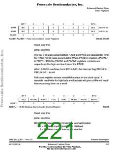
BIT 7
BIt 7
Bit 7
0
6
6
6
0
5
5
5
0
4
4
4
0
3
3
3
0
2
2
2
0
1
1
1
0
BIT 0
$00A4
$00A5
Bit 0
Bit 0
0
PACN1 (hi)
PACN0 (lo)
RESET:
PACN1, PACN0 — Pulse Accumulators Count Registers
$00A4, $00A5
Read: any time
Write: any time
The two 8-bit pulse accumulators PAC1 and PAC0 are cascaded to form
the PACB 16-bit pulse accumulator. When PACB in enabled, (PBEN=1
in PBCTL, $B0) the PACN1 and PACN0 registers contents are
respectively the high and low byte of the PACB.
When PACN1 overflows from $FF to $00, the Interrupt flag PBOVF in
PBFLG ($B1) is set.
Full count register access should take place in one clock cycle. A
separate read/write for high byte and low byte will give a different result
than accessing them as a word.
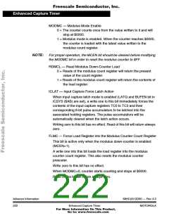
BIT 7
MCZI
0
6
MODMC
0
5
RDMCL
0
4
ICLAT
0
3
FLMC
0
2
MCEN
0
1
MCPR1
0
BIT 0
MCPR0
0
RESET:
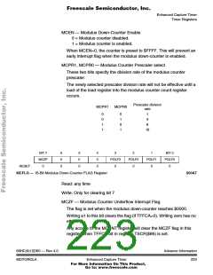
MCCTL — 16-Bit Modulus Down-Counter Control Register
$00A6
Read: any time
Write: any time
MCZI — Modulus Counter Underflow Interrupt Enable
0 = Modulus counter interrupt is disabled.
1 = Modulus counter interrupt is enabled.
68HC(9)12D60 — Rev 4.0
MOTOROLA
Advance Information
221
Enhanced Capture Timer
For More Information On This Product,
Go to: www.freescale.com

 MOTOROLA [ MOTOROLA ]