Freescale Semiconductor, Inc.
Clock Functions
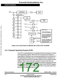
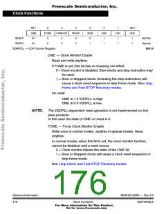
PCLK
5-BIT MODULUS
COUNTER (PR0-PR4)
TO ATD0
and ATD1
÷ 2
÷ 2
REGISTER: SP0BR
BITS: SPR2, SPR1, SPR0
0:0:0
SPI
BIT RATE
÷ 2
÷ 2
÷ 2
0:0:1
0:1:0
MSCAN
CLOCK
EXTALi
CLKSRC
SYSCLK
ECLK
0:1:1
1:0:0
1:0:1
1:1:0
1:1:1
÷ 2
÷ 2
÷ 2
÷ 2
CLKSW
BDM BIT CLOCK:
BCLK
Receive: Detect falling edge,
count 12 ECLKs, Sample input
BKGD IN
SYNCHRONIZER
Transmit 1: Detect falling edge,
count 6 ECLKs while output is
high impedance, Drive out 1 E
cycle pulse high, high imped-
ance output again
BKGD DIRECTION
BKGD
PIN
Transmit 0: Detect falling edge,
Drive out low, count 9 ECLKs,
Drive out 1 E cycle pulse high,
high impedance output
BKGD OUT
LOGIC
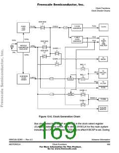
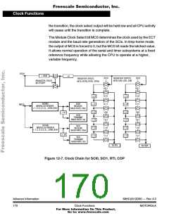
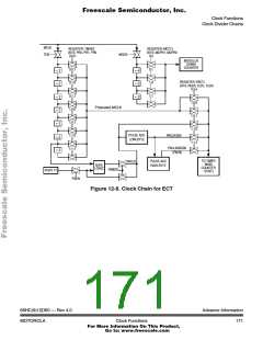
Figure 12-9. Clock Chain for MSCAN, SPI, ATD0, ATD1 and BDM
12.9 Computer Operating Properly (COP)
The COP or watchdog timer is an added check that a program is running
and sequencing properly. When the COP is being used, software is
responsible for keeping a free running watchdog timer from timing out. If
the watchdog timer times out it is an indication that the software is no
longer being executed in the intended sequence; thus a system reset is
initiated. Three control bits allow selection of seven COP time-out
periods. When COP is enabled, sometime during the selected period the
program must write $55 and $AA (in this order) to the COPRST register.
If the program fails to do this the part will reset. If any value other than
$55 or $AA is written, the part is reset.
Advance Information
172
68HC(9)12D60 — Rev 4.0
Clock Functions
MOTOROLA
For More Information On This Product,
Go to: www.freescale.com

 MOTOROLA [ MOTOROLA ]