Freescale Semiconductor, Inc.
SEMICONDUCTOR APPLICATION NOTE
By Wayne Chavez
INTRODUCTION
Today’s low cost accelerometers are highly integrated
devices employing features such as signal conditioning,
filtering, offset compensation and self test. Combining this
featuresetwitheconomicalplasticpackagingrequiresthatthe
signal conditioning circuitry be as small as possible. One
approach is to implement sampled data system and switched
capacitor techniques as in the Motorola accelerometer.
As in all sampled data systems, precautions should be
taken to avoid signal aliasing errors. This application note
describes the Motorola accelerometer and how signal aliasing
can be introduced and more importantly minimized.
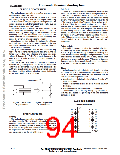
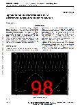
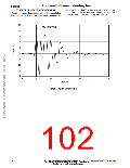
signal at a frequency that is the differencebetweentheoriginal
signal frequency and the sampling rate. A graphical
explanation of aliasing is offered in Figure 1. In this figure, the
upper trace shows a 50 kHz sinusoidal waveform. Note that
when sampled at a 45 kHz rate, denoted by the boxes, a
sinusoidal pattern is formed. Lowpass filtering the sampled
points, to create a continuous signal, produces the 5 kHz
waveform shown in Figure 1 (lower). (The phase shift in the
lower figure is due to the low–pass filter).
Aliased signals, like the one in Figure 1 (lower) are often
unintentionally produced. Signal processing techniques are
well understood and sampling rates are chosen appropriately
(i.e. Nyquist criteria). However, the assumption is that the
signals of interest are well characterized and have a limited
bandwidth. This assumption is not always true, as in the case
of wideband noise.
BACKGROUND
What is aliasing? Simply put, aliasing is the effect of
sampling a signal at an insufficient rate, thus creating another
Figure 1. Aliased Signals
REV 1
2–62
www.motorola.com/semiconductors
Motorola Sensor Device Data
For More Information On This Product,
Go to: www.freescale.com

 MOTOROLA [ MOTOROLA ]