MC1377
APPLICATIONS INFORMATION
S–VHS
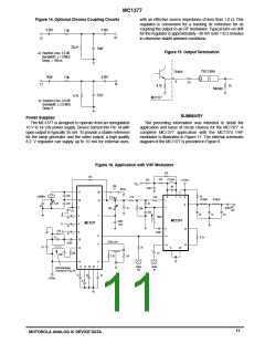
In full RGB systems (Figure 18), three information
components of luminance and color can then be separated
by the use of a comb filter in the monitor or receiver. This
technique has not been widely used in consumer products,
due to cost, but it is rapidly becoming less expensive and
more common. Another technique which is gaining popularity
is S–VHS (Super VHS).
In S–VHS, the chroma and luma information are contained
on separate channels. This allows the bandwidth of both the
chroma and luma channels to be as wide as the monitors
ability to reproduce the extra high frequency information. An
output coupling circuit for the composite chroma using the
TOKO transformer is shown in Figure 19. It is composed of
the bandpass transformer and an output buffer and has the
frequency performance shown in Figure 20. The composite
output (Pin 9) then produces the luma information as well as
composite sync and blanking.
channels are provided from the signal source to the display to
permit unimpaired image resolution. The detail reproduction
of the system is limited only by the signal bandwidth and the
capability of the color display device. Also, higher than
normal sweep rates may be employed to add more lines
within a vertical period and three separate projection picture
tubes can be used to eliminate the “shadow mask” limitations
of a conventional color CRT.
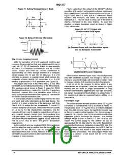
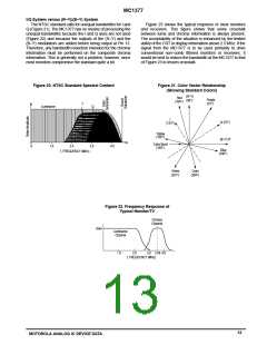
Figure 21 shows the “baseband” components of a studio
NTSC signal. As in the previous example, energy is
concentrated at multiples of the horizontal sweep frequency.
The system is further refined by precisely locating the color
subcarrier midway between luminance spectral components.
This places all color spectra between luminance spectra and
can be accomplished in the MC1377 only if “full interlaced”
external color reference and sync are applied. The individual
Figure 17. Spectra of a Full RGB System
Figure 19. Frequency Response of
Chroma Coupling Circuit
Red
Green
Blue
1.0
2.0
3.0
4–8
f, FREQUENCY (MHz)
–6 dB
Figure 18. S–VHS Output Buffer
+12Vdc
1.0µF
16k 33
100/62pF*
220
1000pF
Composite
Chroma
Out
75
6.8k
f, MHz
13
2.7
3.66
4.5
47/33pF*
**
3.3k
8.2k
+12Vdc
0.1µF
**Refers to different component values used for NTSC/PAL (3.58 MHz/4.43 MHz).
**Toko 166NNF–1026AG
12
MOTOROLA ANALOG IC DEVICE DATA

 MOTOROLA [ MOTOROLA ]