MC1377
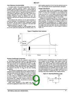
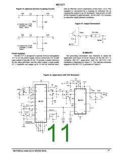
Figure 14. Optional Chroma Coupling Circuits
with an effective source impedance of less than 1.0 Ω. This
regulator is convenient for a tracking dc reference for dc
coupling the output to an RF modulator. Typical turn–on drift
for the regulator is approximately –30 mV over 1 to 2 minutes
in otherwise stable ambient conditions.
0.001
0.001
1.0k
10
13
22µH
39pF
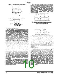
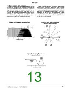
Figure 15. Output Termination
a) Insertion Loss: 3.0 dB
a) Bandwidth: 1.0 MHz
a) Delay: 100 ns
±
≈
75Ω Cable
Output
9
56pF
0.001
1.0k
75
10
13
4.7k
75
Monitor
27pF
4.7k
MC1377
b) Insertion Loss: 9.0 dB
b) Bandwidth:
b) Delay: 0
± 2.0 MHz
SUMMARY
Power Supplies
The MC1377 is designed to operate from an unregulated
10 V to 14 Vdc power supply. Device current into Pin 14 with
open output is typically 35 mA. To provide a stable reference
for the ramp generator and the video output, a high quality
8.2 V regulator can supply up to 10 mA for external uses,
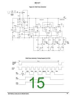
The preceding information was intended to detail the
application and basis of circuit choices for the MC1377. A
complete MC1377 application with the MC1374 VHF
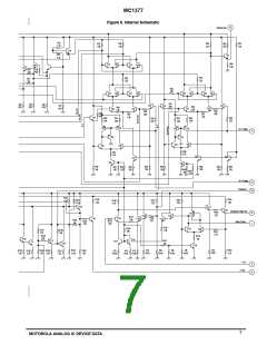
modulator is illustrated in Figure 17. The internal schematic
diagram of the MC1377 is provided in Figure 8.
Figure 16. Application with VHF Modulator
470
47k
470
0.12µH
470
+12Vdc
V
CC
PAL
56
0.001
NTSC
17
20
16
220
220
3.58MHz
10
75
0.33
2.7k
2.2k
6
1
7
4
8
9
8.2V
53k
Ref
µ
H
0.33µH
18
2
5–25
47
RF
0.001
3
0.1
6.8k
+
Out
0.1
+
120
S
R
22
47
22
3
4
1
10µH
15
MC1374
0.001
mica
MC1377
G
+
+
15
15
2
12
13
3.3k
B
5
0.001
9
8
11
5.1k
47
10
Delay Line
1.2k
0.001
14
0.1
75
13
5
10
+
220
1.0
100
1.2k
14
6
11 12 19 15
7
Video
Out
Audio
In
Color Bandpass
Transformer (Fig. 24)
0.1
.01
.01
+12Vdc
0.1
11
MOTOROLA ANALOG IC DEVICE DATA

 MOTOROLA [ MOTOROLA ]