Ver. 1.1
MITSUBISHI LSIs
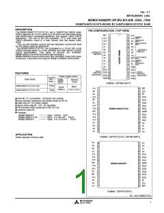
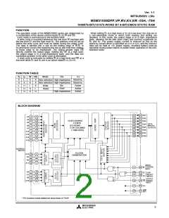
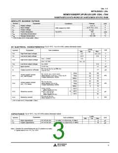
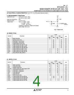
M5M51008DFP,VP,RV,KV,KR -55H, -70H
1048576-BIT(131072-WORD BY 8-BIT)CMOS STATIC RAM
POWER DOWN CHARACTERISTICS
(1) ELECTRICAL CHARACTERISTICS
(Ta=0~70°C, unless otherwise noted)
Test conditions
Limits
Typ
Symbol
VCC (PD)
VI (S1)
Parameter
Power down supply voltage
Chip select input S1
Unit
V
Min
2.0
2.2
Max
2.2V£Vcc(PD)
2V£Vcc(PD)£2.2V
4.5V£Vcc(PD)
Vcc(PD)<4.5V
VCC = 3V
V
V
Vcc(PD)
0.8
0.2
1
VI (S2)
Chip select input S2
~25°C
~40°C
~70°C
1) S2 £ 0.2V, other inputs = 0~3V
2) S1 ³ VCC–0.2V,S2 ³ VCC–0.2V
other inputs = 0~3V
-H
3
µA
ICC (PD)
Power down supply current
10
(2) TIMING REQUIREMENTS (Ta=0~70°C, unless otherwise noted )
Limits
Typ
Symbol
Parameter
Test conditions
Unit
Min
0
Max
tsu (PD)
trec (PD)
Power down set up time
Power down recovery time
ns
5
ms
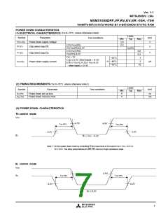
(3) POWER DOWN CHARACTERISTICS
S1 control mode
VCC
4.5V
4.5V
tsu (PD)
trec (PD)
2.2V
2.2V
S1
S1 ³ VCC – 0.2V
Note 7: On the power down mode by controlling S1,the input level of S2 must be S2 ³ Vcc - 0.2V or
S2 £ 0.2V. The other pins(Address,I/O,WE,OE) can be in high impedance state.
S2 control mode
VCC
4.5V
4.5V
S2
tsu (PD)
trec (PD)
0.2V
0.2V
S2 £ 0.2V
MITSUBISHI
ELECTRIC
7

 MITSUBISHI [ Mitsubishi Group ]