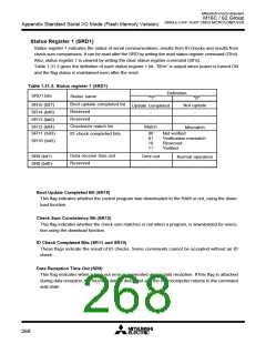
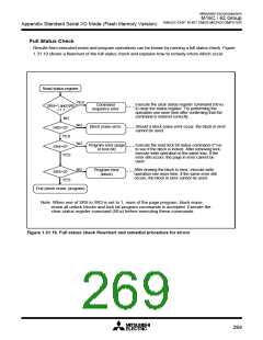
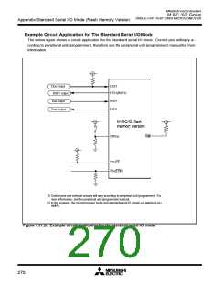
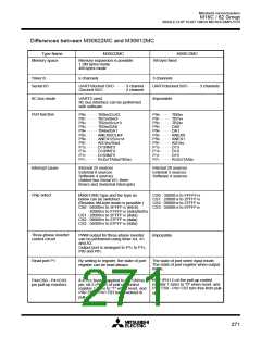
Mitsubishi microcomputers
M16C / 62 Group
SINGLE-CHIP 16-BIT CMOS MICROCOMPUTER
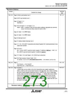
Version
REV.H5
Revision
date
Contents for change
00.7.4
Page 34, Table 1.12.2
Normal mode, microprocessor mode, _C__S___0_ area
0300016 to FFFFF16 --->3000016 to FFFFF16
Expansion mode 1, microprocessor mode, PM13=1, _C__S___0_ area
0600016 to FFFFF16 --->0600016 to BFFFF16
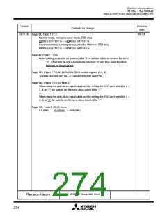
Page 49, Figure 1.13.6
Note: Writing a value to an address after “1” is written to this bit returns the bit to
“0” . Other bits do not automatically return to “0” and they must therefore
be reset by the program.
Page 149, Figure 1.19.32, bit 5 of the SI/Oi control register (i=3, 4)
Transfer direction lect bit --->Transfer direction select bit
Page 149, Figure 1.19.32, Note 2
When using the port as an input/output port by setting the SI/Oi port select bit (i =
3, 4) to “1”, be sure to set the sync clock select bit to “1”.
--->
When using the port as an input/output port by setting the SI/Oi port select bit (i =
3, 4) to “0”, be sure to set the sync clock select bit to “1”.
Page 198, Table 1.26.23, tCONV
9.8 (Min)
VCC(Max) --->9.8 (Min)
M16C/62 Group data sheet
Revision history
274

 MITSUBISHI [ Mitsubishi Group ]