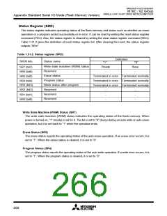
Mitsubishi microcomputers
M16C / 62 Group
SINGLE-CHIP 16-BIT CMOS MICROCOMPUTER
Appendix Standard Serial I/O Mode (Flash Memory Version)
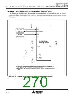
Example Circuit Application for The Standard Serial I/O Mode
The below figure shows a circuit application for the standard serial I/O mode. Control pins will vary ac-
cording to peripheral unit (programmer), therefore see the peripheral unit (programmer) manual for more
information.
Clock input
CLK1
RTS1(BUSY)
BUSY output
R
XD1
Data input
T
XD1
Data output
M16C/62 flash
memory version
CNVss
NMI
P5
0(CE)
P5
5(EPM)
(1) Control pins and external circuitry will vary according to peripheral unit (programmer). For
more information, see the peripheral unit (programmer) manual.
(2) In this example, the microprocessor mode and standard serial I/O mode are switched via a
switch.
Figure 1.31.20. Example circuit application for the standard serial I/O mode
270

 MITSUBISHI [ Mitsubishi Group ]