Mitsubishi microcomputers
M16C / 62 Group
SINGLE-CHIP 16-BIT CMOS MICROCOMPUTER
Appendix Standard Serial I/O Mode (Flash Memory Version)
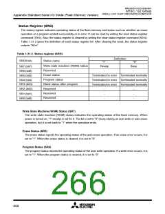
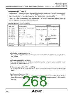
Status Register 1 (SRD1)
Status register 1 indicates the status of serial communications, results from ID checks and results from
check sum comparisons. It can be read after the SRD by writing the read status register command (7016).
Also, status register 1 is cleared by writing the clear status register command (5016).
Table 1.31.3 gives the definition of each status register 1 bit. “0016” is output when power is turned ON
and the flag status is maintained even after the reset.
Table 1.31.3. Status register 1 (SRD1)
Definition
SRD1 bits
Status name
"1"
"0"
Boot update completed bit
Reserved
SR15 (bit7)
SR14 (bit6)
SR13 (bit5)
Not update
Update completed
-
-
Reserved
-
-
Checksum match bit
ID check completed bits
Match
SR12 (bit4)
SR11 (bit3)
Mismatch
00
01
10
11
Not verified
Verification mismatch
Reserved
SR10 (bit2)
Verified
Data receive time out
Reserved
SR9 (bit1)
SR8 (bit0)
Time out
-
Normal operation
-
Boot Update Completed Bit (SR15)
This flag indicates whether the control program was downloaded to the RAM or not, using the down-
load function.
Check Sum Consistency Bit (SR12)
This flag indicates whether the check sum matches or not when a program, is downloaded for execu-
tion using the download function.
ID Check Completed Bits (SR11 and SR10)
These flags indicate the result of ID checks. Some commands cannot be accepted without an ID
check.
Data Reception Time Out (SR9)
This flag indicates when a time out error is generated during data reception. If this flag is attached
during data reception, the received data is discarded and the microcomputer returns to the command
wait state.
268

 MITSUBISHI [ Mitsubishi Group ]