Mitsubishi microcomputers
M16C / 62 Group
SINGLE-CHIP 16-BIT CMOS MICROCOMPUTER
CPU Rewrite Mode (Flash Memory Version)
Data Protect Function (Block Lock)
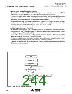
Each block in Figure 1.28.1 has a nonvolatile lock bit to specify that the block be protected (locked)
against erase/write. The lock bit program command is used to set the lock bit to 0 (locked). The lock bit of
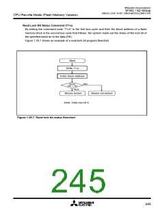
each block can be read out using the read lock bit status command.
Whether block lock is enabled or disabled is determined by the status of the lock bit and how the flash
memory control register 0’s lock bit disable bit is set.
(1) When the lock bit disable bit = 0, a specified block can be locked or unlocked by the lock bit status
(lock bit data). Blocks whose lock bit data = 0 are locked, so they are disabled against erase/write.
On the other hand, the blocks whose lock bit data = 1 are not locked, so they are enabled for erase/
write.
(2) When the lock bit disable bit = 1, all blocks are nonlocked regardless of the lock bit data, so they are
enabled for erase/write. In this case, the lock bit data that is 0 (locked) is set to 1 (nonlocked) after
erasure, so that the lock bit-actuated lock is removed.
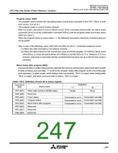
Status Register
The status register indicates the operating status of the flash memory and whether an erase or program
operation has terminated normally or in an error. The content of this register can be read out by only
writing the read status register command (7016). Table 1.29.2 details the status register.
The status register is cleared by writing the Clear Status Register command (5016).
After a reset, the status register is set to “8016.”
Each bit in this register is explained below.
Write state machine (WSM) status (SR7)
After power-on, the write state machine (WSM) status is set to 1.
The write state machine (WSM) status indicates the operating status of the device, as for output on the
____
RY/BY pin. This status bit is set to 0 during auto write or auto erase operation and is set to 1 upon
completion of these operations.
Erase status (SR5)
The erase status informs the operating status of auto erase operation to the CPU. When an erase
error occurs, it is set to 1.
The erase status is reset to 0 when cleared.
246

 MITSUBISHI [ Mitsubishi Group ]