Mitsubishi microcomputers
M16C / 62 Group
SINGLE-CHIP 16-BIT CMOS MICROCOMPUTER
Description (Flash Memory Version)
Flash Memory
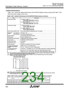
The M16C/62 (flash memory version) contains the DINOR (DIvided bit line NOR) type of flash memory that
can be rewritten with a single voltage of 5 V or 3.3 V. For this flash memory, three flash memory modes are
available in which to read, program, and erase: parallel I/O and standard serial I/O modes in which the flash
memory can be manipulated using a programmer and a CPU rewrite mode in which the flash memory can
be manipulated by the Central Processing Unit (CPU). Each mode is detailed in the pages to follow.
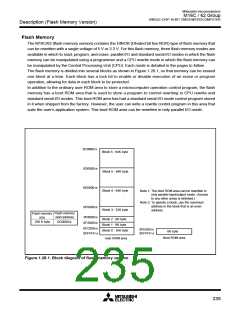
The flash memory is divided into several blocks as shown in Figure 1.28.1, so that memory can be erased
one block at a time. Each block has a lock bit to enable or disable execution of an erase or program
operation, allowing for data in each block to be protected.
In addition to the ordinary user ROM area to store a microcomputer operation control program, the flash
memory has a boot ROM area that is used to store a program to control rewriting in CPU rewrite and
standard serial I/O modes. This boot ROM area has had a standard serial I/O mode control program stored
in it when shipped from the factory. However, the user can write a rewrite control program in this area that
suits the user’s application system. This boot ROM area can be rewritten in only parallel I/O mode.
0C000016
Block 6 : 64K byte
0D000016
Block 5 : 64K byte
0E000016
Block 4 : 64K byte
Note 1: The boot ROM area can be rewritten in
only parallel input/output mode. (Access
to any other areas is inhibited.)
Note 2: To specify a block, use the maximum
address in the block that is an even
address.
0F000016
Block 3 : 32K byte
Flash memory
start address
Flash memory
size
0F800016
0FA00016
Block 2 : 8K byte
Block 1 : 8K byte
Block 0 : 16K byte
256 K byte
0C000016
0FC00016
0FFFFF16
0FE00016
8K byte
0FFFFF16
Boot ROM area
User ROM area
Figure 1.28.1. Block diagram of flash memory version
235

 MITSUBISHI [ Mitsubishi Group ]