Mitsubishi microcomputers
M16C / 62 Group
SINGLE-CHIP 16-BIT CMOS MICROCOMPUTER
Description (Flash Memory Version)
Outline Performance
Table 1.28.1 shows the outline performance of the M16C/62 (flash memory version) and Table 1.28.2
shows the power supply current( Typ.).
Table 1.28.1. Outline Performance of the M16C/62 (flash memory version)
Item
Performance
Power supply voltage
5V version: 2.7V to 5.5 V
(f(XIN)=16MHz, without wait, 4.2V to 5.5V,
f(XIN)=10MHz, with one wait, 2.7V to 5.5V)
3V version: 2.4V to 3.6 V
(f(XIN)=10MHz, without wait, 2.7V to 3.6V,
f(XIN)=7MHz, without wait, 2.4V to 3.6V)
5V version: 4.2V to 5.5 V
Program/erase voltage
(f(XIN)=12.5MHz, with one wait,
f(XIN)=6.25MHz, without wait)
3V version: 2.7V to 3.6 V
(f(XIN)=10MHz, with one wait,
f(XIN)=6.25MHz, without wait)
Flash memory operation mode
Three modes (parallel I/O, standard serial I/O, CPU rewrite)
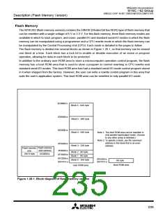
Erase block
division
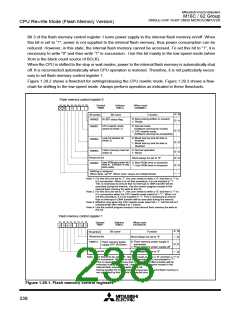
See Figure 1.28.1
User ROM area
Boot ROM area
One division (8 Kbytes) (Note 1)
In units of pages (in units of 256 bytes)
Collective erase/block erase
Program/erase control by software command
Protected for each block by lock bit
8 commands
Program method
Erase method
Program/erase control method
Protect method
Number of commands
Program/erase count
100 times
Parallel I/O and standard serial modes are supported.
ROM code protect
3V version main clock input
oscillation frequency(Max.)
(Note2)
10MHz (VCC=2.7V to 3.6V,without wait)
10 X VCC - 17 MHz (VCC=2.4V to 2.7V,without wait)
3V version power supply
current (Notes 3, 4)
12.0mA(Typ.), 21.25mA(Max.) (VCC=3V, f(XIN)=10MHz, square wave, no division, without wait)
40µA(Typ.) (VCC=3V, f(XCIN)=32kHz, square wave, without wait) [operate in RAM]
700µA(Typ.) (VCC=3V, f(XCIN)=32kHz, square wave, without wait) [operate in flash memory]
Note1: The boot ROM area contains a standard serial I/O mode control program which is stored in it when shipped from the factory.
This area can be erased and programmed in only parallel I/O mode.
Note2: Refer to recommended operating conditions about 5 V version. 3V version relationship between main clock oscillation
frequency and supply voltage are as follows.
Main clock input oscillation frequency
(flash memory 3V version, without wait)
10.0
10 X VCC - 17MH
Z
7.0
0.0
2.4
Supply voltage[V]
2.7
3.6
(BCLK: no division)
Note3: Refer to electric characteristic about 5V version.
Note4: A standard value in stop and wait modes do not depend on a kind of memory to have built-in and is the same class. Refer to
electric characteristic in VCC=3V.
Table 1.28.2. Power supply current (typ.) of the M16C/62 (flash memory version)
Standard (Typ.)
Remark
Parameter
Measuring condition
Read
Program
28mA
-
Erase
25mA
-
Division by 4 in program/erase
5V power supply current(5V version) f(XIN)=16MHz, without wait, No division
3V power supply current(5V version) f(XIN)=10MHz, with wait, No division
3V power supply current(3V version) f(XIN)=10MHz, without wait, No division
35mA
13.5mA
12mA
Division by 2 in program/erase
17mA
14mA
234

 MITSUBISHI [ Mitsubishi Group ]