Mitsubishi microcomputers
M16C / 61 Group
SINGLE-CHIP 16-BIT CMOS MICROCOMPUTER
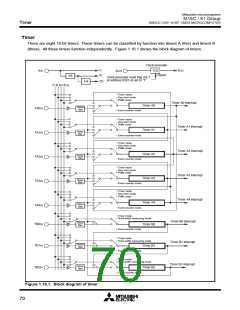
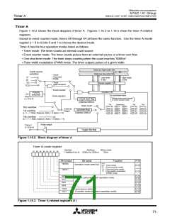
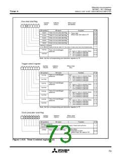
Timer A
(1) Timer mode
In this mode, the timer counts an internally generated count source. (See Table 1.16.1.) Figure 1.16.6
shows the timer Ai mode register in timer mode.
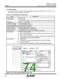
Table 1.16.1. Specifications of timer mode
Item
Count source
Count operation
Specification
f1, f8, f32, fC32
• Down count
•
When the timer underflows, it reloads the reload register contents before continuing counting
Divide ratio
1/(n+1) n : Set value
Count start condition
Count stop condition
Count start flag is set (= 1)
Count start flag is reset (= 0)
Interrupt request generation timing When the timer underflows
TAiIN pin function
TAiOUT pin function
Read from timer
Write to timer
Programmable I/O port or gate input
Programmable I/O port or pulse output
Count value can be read out by reading timer Ai register
• When counting stopped
When a value is written to timer Ai register, it is written to both reload register and counter
• When counting in progress
When a value is written to timer Ai register, it is written to only reload register
(Transferred to counter at next reload time)
• Gate function
Select function
Counting can be started and stopped by the TAiIN pin’s input signal
• Pulse output function
Each time the timer underflows, the TAiOUT pin’s polarity is reversed
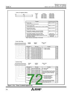
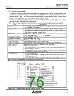
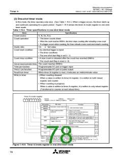
Timer Ai mode register
b7 b6 b5 b4 b3 b2 b1 b0
Symbol
Address
When reset
0016
TAiMR(i=0 to 4) 039616 to 039A16
0
0 0
Bit symbol
Bit name
Function
R W
b1 b0
Operation mode
select bit
TMOD0
TMOD1
MR0
0 0 : Timer mode
Pulse output function
select bit
0 : Pulse is not output
(TAiOUT pin is a normal port pin)
1 : Pulse is output (Note 1)
(TAiOUT pin is a pulse output pin)
b4 b3
Gate function select bit
MR1
MR2
0 X (Note 2): Gate function not available
(TAiIN pin is a normal port pin)
1 0 : Timer counts only when TAiIN pin is
held “L” (Note 3)
1 1 : Timer counts only when TAiIN pin is
held “H” (Note 3)
MR3
0 (Must always be fixed to “0” in timer mode)
b7 b6
TCK0
Count source select bit
0 0 : f
1
8
0 1 : f
TCK1
1 0 : f32
1 1 : fC32
Note 1: The settings of the corresponding port register and port direction register
are invalid.
Note 2: The bit can be “0” or “1”.
Note 3: Set the corresponding port direction register to “0”.
Figure 1.16.6. Timer Ai mode register in timer mode
74

 MITSUBISHI [ Mitsubishi Group ]