Mitsubishi microcomputers
M16C / 61 Group
SINGLE-CHIP 16-BIT CMOS MICROCOMPUTER
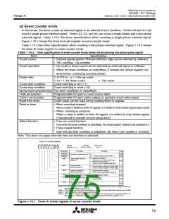
Timer A
Timer A
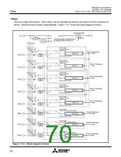
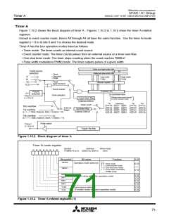
Figure 1.16.2 shows the block diagram of timer A. Figures 1.16.3 to 1.16.5 show the timer A-related
registers.
Except in event counter mode, timers A0 through A4 all have the same function. Use the timer Ai mode
register (i = 0 to 4) bits 0 and 1 to choose the desired mode.
Timer A has the four operation modes listed as follows:
• Timer mode: The timer counts an internal count source.
• Event counter mode: The timer counts pulses from an external source or a timer over flow.
• One-shot timer mode: The timer stops counting when the count reaches “000016”.
• Pulse width modulation (PWM) mode: The timer outputs pulses of a given width.
Data bus high-order bits
Clock source
selection
Data bus low-order bits
• Timer
• One shot
• PWM
f
1
Low-order
8 bits
High-order
8 bits
f8
• Timer
(gate function)
f
32
Reload register (16)
f
C32
• Event counter
Clock selection
Counter (16)
Polarity
selection
Up count/down count
TAiIN
Always down count except
in event counter mode
(i = 0 to 4)
Count start flag
(Address 038016
)
TAi
Addresses
TAj
TAk
Down count
Timer A0 038716 038616
Timer A1 038916 038816
Timer A2 038B16 038A16 Timer A1 Timer A3
Timer A3 038D16 038C16 Timer A2 Timer A4
Timer A4 038F16 038E16 Timer A3 Timer A0
Timer A4 Timer A1
Timer A0 Timer A2
TB2 overflow
External
trigger
Up/down flag
TAj overflow
(j = i – 1. Note, however, that j = 4 when i = 0)
(Address 038416
)
TAk overflow
(k = i + 1. Note, however, that k = 0 when i = 4)
Pulse output
TAiOUT
(i = 0 to 4)
Toggle flip-flop
Figure 1.16.2. Block diagram of timer A
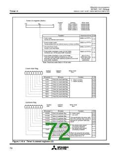
Timer Ai mode register
Symbol
Address
When reset
0016
b7 b6 b5 b4 b3 b2 b1 b0
TAiMR(i=0 to 4) 039616 to 039A16
R W
Bit symbol
TMOD0
Bit name
Function
b1 b0
Operation mode select bit
0 0 : Timer mode
0 1 : Event counter mode
1 0 : One-shot timer mode
1 1 : Pulse width modulation
(PWM) mode
TMOD1
MR0
MR1
MR2
MR3
TCK0
TCK1
Function varies with each operation mode
Count source select bit
(Function varies with each operation mode)
Figure 1.16.3. Timer A-related registers (1)
71

 MITSUBISHI [ Mitsubishi Group ]