Mitsubishi microcomputers
M16C / 61 Group
SINGLE-CHIP 16-BIT CMOS MICROCOMPUTER
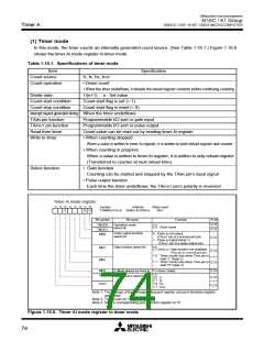
Timer
Timer
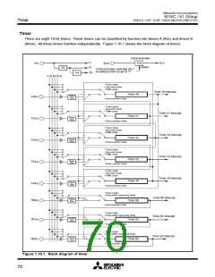
There are eight 16-bit timers. These timers can be classified by function into timers A (five) and timers B
(three). All these timers function independently. Figure 1.16.1 shows the block diagram of timers.
Clock prescaler
f
1
8
fC32
XIN
1/32
Reset
X
CIN
f
1/8
Clock prescaler reset flag (bit 7
at address 038116) set to “1”
f
32
1/4
f1 f8 f32 fC32
• Timer mode
• One-shot mode
• PWM mode
Timer A0 interrupt
Timer A1 interrupt
Timer A2 interrupt
Timer A3 interrupt
Timer A4 interrupt
Timer A0
Noise
filter
TA0IN
TA1IN
TA2IN
TA3IN
• Event counter mode
• Timer mode
• One-shot mode
• PWM mode
Timer A1
Noise
filter
• Event counter mode
• Timer mode
• One-shot mode
• PWM mode
Timer A2
Timer A3
Timer A4
Noise
filter
• Event counter mode
• Timer mode
• One-shot mode
• PWM mode
Noise
filter
• Event counter mode
• Timer mode
• One-shot mode
• PWM mode
Noise
filter
TA4IN
TB0IN
• Event counter mode
• Timer mode
• Pulse width measuring mode
Timer B0 interrupt
Timer B1 interrupt
Noise
filter
Timer B0
• Event counter mode
• Timer mode
• Pulse width measuring mode
Noise
filter
TB1IN
TB2IN
Timer B1
• Event counter mode
• Timer mode
• Pulse width measuring mode
Timer B2 interrupt
Noise
filter
Timer B2
• Event counter mode
Figure 1.16.1. Block diagram of timer
70

 MITSUBISHI [ Mitsubishi Group ]