Mitsubishi microcomputers
M16C / 61 Group
_N___M___I_ Interrupt
SINGLE-CHIP 16-BIT CMOS MICROCOMPUTER
______
INT Interrupt
________
________
INT0 to INT2 are triggered by the edges of external inputs. The edge polarity is selected using the polarity
select bit.
______
NMI Interrupt
______
______
______
An NMI interrupt is generated when the input to the P85/NMI pin changes from “H” to “L”. The NMI interrupt
is a non-maskable external interrupt. The pin level can be checked in the port P85 register (bit 5 at address
03F016).
This pin cannot be used as a normal port input.
Key Input Interrupt
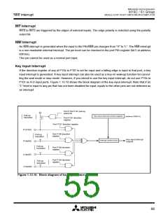
If the direction register of any of P104 to P107 is set for input and a falling edge is input to that port, a key
input interrupt is generated. A key input interrupt can also be used as a key-on wakeup function for cancel-
ling the wait mode or stop mode. However, if you intend to use the key input interrupt, do not use P104 to
P107 as A-D input ports. Figure 1.13.10 shows the block diagram of the key input interrupt. Note that if an
“L” level is input to any pin that has not been disabled for input, inputs to the other pins are not detected as
an interrupt.
Port P10
4-P107 pull-up
select bit
Pull-up
Key input interrupt control register
(address 004D16
)
transistor
Port P10
register
7 direction
Port P10
7
direction register
P10
7
/KI
3
2
Port P10
register
6 direction
Pull-up
transistor
Key input interrupt
request
Interrupt control circuit
P10
6
/KI
Pull-up
transistor
Port P10
register
5
direction
direction
P105/KI1
Port P10
register
4
Pull-up
transistor
P104/KI0
Figure 1.13.10. Block diagram of key input interrupt
55

 MITSUBISHI [ Mitsubishi Group ]