Mitsubishi microcomputers
M16C / 61 Group
SINGLE-CHIP 16-BIT CMOS MICROCOMPUTER
Interrupt
Saving Registers
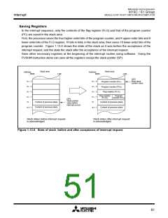
In the interrupt sequence, only the contents of the flag register (FLG) and that of the program counter
(PC) are saved in the stack area.
First, the processor saves the four higher-order bits of the program counter, and 4 upper-order bits and 8
lower-order bits of the FLG register, 16 bits in total, in the stack area, then saves 16 lower-order bits of the
program counter. Figure 1.13.6 shows the state of the stack as it was before the acceptance of the
interrupt request, and the state the stack after the acceptance of the interrupt request.
Save other necessary registers at the beginning of the interrupt routine using software. Using the
PUSHM instruction alone can save all the registers except the stack pointer (SP).
Stack area
Stack area
Address
MSB
Address
MSB
LSB
LSB
[SP]
New stack
pointer value
m – 4
m – 3
m – 2
m – 1
m
m – 4
m – 3
m – 2
m – 1
m
Program counter (PC
Program counter (PC
L
)
M
)
Flag register (FLG )
L
Flag register
(FLG
Program
counter (PC )
H
)
H
[SP]
Stack pointer
value before
interrupt occurs
Content of previous stack
Content of previous stack
Content of previous stack
Content of previous stack
m + 1
m + 1
Stack status before interrupt request
is acknowledged
Stack status after interrupt request
is acknowledged
Figure 1.13.6. State of stack before and after acceptance of interrupt request
51

 MITSUBISHI [ Mitsubishi Group ]