PDSP1601 MC
(1)
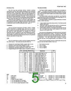
Priority encode the 16 bit input to the Barrel Shifter and
SV3
SV2
SV1 SV0
Shift
place the 4 bit value in either of the R1 or R2 registers and
output the value on the SV port (if enabled by SVOE).
0
0
0
0
0
0
0
0
1
1
1
1
1
1
1
1
0
0
0
0
1
1
1
1
0
0
0
0
1
1
1
1
0
0
1
1
0
0
1
1
0
0
1
1
0
0
1
1
0
1
0
1
0
1
0
1
0
1
0
1
0
1
0
1
No shift
1 place
(2)
Shift the 16 bit input by the amount indicated by the
2 places
3 places
4 places
5 places
6 places
7 places
8 places
9 places
10 places
11 places
12 places
13 places
14 places
15 places
Priority Encoder such that the output from the Barrel Shifter is
a normalised value.
SV Input
If the SV port is selected as the source of the shift value,
thentheinputtotheBarrelShifterisshiftedbythevaluestored
in the internal SV register.
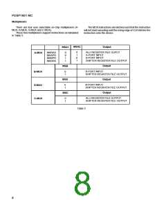
SVOE
The SV port acts as an input or an output depending upon
the IS0-3 instruction. If the user does not wish to use the
normalise instructions, then the SV port mat be forced to be
Table 3 Barrel shifter codes
input only by typing SVOE control high. In this mode the SV
port may be considered an extension of the instruction inputs.
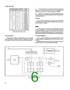
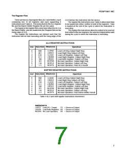
R1 and R2 Registers
Priority Encoder
The R1 and R2 registers may be loaded from the Priority
Encoder (NRMR1 and NRMR2) or from the SV input (LR1SV,
LR2SV).
If the priority encoder is selected as the source of the shift
value (instructions:- NRMXX, NRMR1, MRMRZ), then within
one 200ns cycle or two 100ns cycles, the shift circuitry will:
Whilst the latter two instructions are executing, the Barrel
Shifter will pass its input to the output unshifted.
16
4
INSTRUCTION
IS0-3
DECODE
PRIORITY ENCODER
4
4
MUX
SV
MUX
R1
MUX
SVOE
R2
Fig.3 Shift control block
6

 MITEL [ MITEL NETWORKS CORPORATION ]