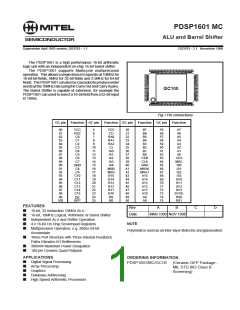
PDSP1601 MC
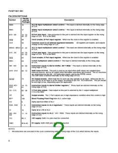
PIN DESCRIPTIONS
Pin No.
Description
Symbol
MSB
(GG100
Package)
ALU B-input multiplexer select control.1 This input is latched internally on the rising edge
16
17
of CLK.
Shifter Input multiplexer select control.1 This input is latched internally on the rising edge
MSS
of CLK.
B Port data Input. Data presented to this port is latched into the input register on the rising
edge of CLK. B15 is the MSB.
B15 - B0
18 - 25
30 - 37
Clock enable, B Port input register. When low the clock to this register is enabled.
38
39
CEB
Common clock to all internal registered elements. All registers are loaded, and outputs
change on the rising edge of CLK.
CLK
ALU A-input multiplexer select control.1 This input are latched internally on the rising edge
MSA0 - MSA1
A15 - A0
41 - 42
of CLK.
A Port data Input. Data presented to this port is latched into the input register on the rising
edge of CLK. B15 is the MSB.
43 - 50
55 - 62
Clock enable, A Port input register. When low the clock to this register is enabled.
63
64
CEA
C-Port multiplexer select control.1 This input is latched internally on the rising edge
of CLK.
MSC
Instruction inputs to Barrel Shifter, IS3 = MSB.1 This input is latched internally on the
IS0 - IS3
65 - 68
69 - 72
rising edge of CLK.
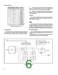
Shift Value I/O Port. This port is used as an input when shift values are supplied form
external sources, and as an output when Normalise operations are invoked. The I/O functions
SV0 - SV3
are determined by the IS0 - IS3 instruction inputs, and by the SVOE control.
The shift value is latched internally on the rising edge of CLK.
SV Output enable. When high the SV port can only operate as an input. When low the SV
port can act as an input or as an output, according to the IS0 - IS3 instruction. This pin should
be tied high or low, depending upon the application.
73
SVOE
Instruction inputs to Barrel Shifter registers.1 These input are latched internally on the
rising edge of CLK.
RS0, RS1
RS2
74 - 75
81
C Port data output. Data output on this port is selected by the C output multiplexer.
C15 is the MSB
C0 - C15
82 - 98
Output enable. The C Port outputs are in high impedance condition when this control is high
Block Floating Point Flag from ALU, active high.
OE
99
BFP
100
6
Carry out from MSB of ALU
CO
Instruction inputs to ALU registsers.1 These inputs are latched interally on the rising
edge of CLK.
RA0 - RA2
7 - 9
Carry in to LSB of ALU
CI
10
Instruction inputs to ALU.1 IA4 = MSB. These inputs are latched internally on the rising
edge of CLK.
IA0 - IA3
IA4
11 - 14
+5V supply: Both Vcc pins must be connected.
Vcc
80, 5
0V supply: Both GND pins must be connected.
GND
90 & 40
NOTES
1. All instructions are executed in the cycle commencing with the rising edge of the CLK which latches the inputs.
2

 MITEL [ MITEL NETWORKS CORPORATION ]