PDSP1601 MC
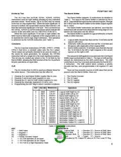
A INPUT
16
B INPUT
16
CEA
CEB
MSS
B REG
A REG
MSA0-1
2
MSB
A MUX
A
B MUX
B
S MUX
BFP
CO
IA0-4
5
IS0-3
SV0-3
SHIFT
CONTROL
BARREL SHIFTER
ALU
CI
SVOE
RAD-2
RS0-2
ALU REG FILE
SHIFTER REG FILE
3
3
LEFT REG.
RIGHT REG.
LEFT REG.
RIGHT REG.
MSC
C MUX
OE
16
COUT
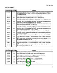
Fig.2 PDSP1601 block diagram
FUNCTIONAL DESCRIPTION
The PDSP1601 contains four main blocks: the ALU, the
Barrel Shifter and the two Register Files.
activetheALUresultmusthaveoverflowedintothe16th(sign)
bit, (this flag is only valid whilst the most significant 16 bit byte
is being processed). The zero condition is active if the result
from the ALU is equal to zero. For multiprecision operations
the zero flag must be active for all of the 16 bit bytes of an
extended word.
The BFP flag is programmed by executing on of the four
SBFXXinstructions(seeTable1). Duringtheexecutionofany
of these four instructions, the output of the ALU is forced to
zero.
The ALU
The ALU supports 32 instructions as detailed in Table 1.
The inputs to the ALU are selected by the A and B MUXs.
Data will fall through from the selected register through the A
or B input MUXs and the ALU to the ALU output register file in
100ns.
The ALU instructions are latched, such that the instruction
will not start executing until the rising edge of CLK latches the
instruction into the device.
Multicycle/Cascade Operation
The ALU accepts a carry in from the CI input and supplies
a carry out to the CO output. Additionally, at the end of each
cycle, the carry out from the ALU is loaded into an internal 1
bit register, so that it is available as an input to the ALU on the
next cycle. In the manner, Multicycle, multiprecisiion
operations are supported. (See MULTICYCLE CASCADE
OPERATIONS).
The ALU arithmetic instructions contain two or three
options for each arithemtic operation.
The ALU is designed to operate with two's complement
arithmetic, requiring a one to be added to the LSB for all
subtractoperations. Theinstructionssetincludesinstructions
thatwillforceaoneintotheLSB, e.g. MIAX1, AMBX1, BMAX1
(see Table 1).
These instructions are used for the least significant 16 bits
of any subtract operation.
BFP Flag
The user has an option of cascading multiple devices, or
multicycling a single device to extend the arithmetic precision.
Should the user cascade multiple devices, then the cascaded
arithmetic instructions using the external CI input should be
employed for all but the least significant 16 bits, e.g. MIACI,
APBCI, BMACI (see Table 1).
Should the user multicycle a single device, then the
Multicycle Arithmetic instructions, using the internally
registered CO bit should be employed for all but the least
significant 16 bits, e.g. MIACO, APBCO, AMBCO, BMACO
(see Table 1).
The ALU has a user programmable BFP flag. This flag
may be programmed to become active at any one of four
conditions. Two of these conditions are intended to support
Block Floating Point operations, in that they provide flags
indicating that the ALU result is within a factor of two or four of
overflowing the 16 bit number range. For multiprecision
operations the flag is only valid whilst the most significant 16
bit byte is being processed. In this manner the BFP flag may
be used over any extended word width.
The remaining two conditions detect either an overflow
condition or a zero result. For the overflow condition to be
3

 MITEL [ MITEL NETWORKS CORPORATION ]