PDSP1601 MC
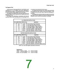
The Register Files
Therearetwoon-chipregisterfiles(ALUandShifter),each
containing two 16 bit registers and each supporting 8
instructions(seeTable4). TheinstructionsfotheALUregister
file and the Barrel Shifter Register file are the same.
The Inputs to the register files come from either the ALU or
the Barrel Shifter, and are loaded into the Register files on the
rising edge of CLK.
CLK latches the instruction into the device.
The register file instructions (see Table 4) allow input data
to be loaded into either, neither or both of the registers. Data
is loaded at the end of the cycle in which the instruction is
executing.
The register file instructions allow the output to be sourced
fromeitherofthetworegisters,theselectedoutputwillbevalid
during the cycle in which the instruction is executing.
The register file instructions are latched such that the
instruction will not start executing until the rising edge of the
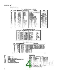
ALU REGISTER INSTRUCTIONS
Mnemonic
Inst RA2-RA0
Operation
LLRRR
LRRLR
LLRLR
LRRRR
LBRLR
NOPRR
NOPLR
NOPPS
0
1
2
3
4
5
6
7
000
001
010
011
100
101
110
111
Load Left Reg Output Right Reg
Load Right Reg Output Left Reg
Load Left Register, Output Left Reg
Load Right Register, Output Right Reg
Load Both Register, Output Left Reg
No load Operation, Output Right Reg
No load Operation, Output Left Reg
No load Operation, Pass ALU Result
SHIFTER REGISTER INSTRUCTIONS
Mnemonic
Inst RA2-RA0
Operation
LLRRR
LRRLR
LLRLR
LRRRR
LBRLR
NOPRR
NOPLR
NOPPS
0
1
2
3
4
5
6
7
000
001
010
011
100
101
110
111
Load Left Reg Output Right Reg
Load Right Reg Output Left Reg
Load Left Register, Output Left Reg
Load Right Register, Output Right Reg
Load Both Register, Output Left Reg
No load Operation, Output Right Reg
No load Operation, Output Left Reg
No load Operation, Pass Barrel Shifter Result
Table 4 ALU and shift register instructions mnemonics
MNEMONICS
LXXYY Load XX = Target,
YY = Source of Output
LBOXX Load Both Registers, XX = Source of Output
NOPXX No Load Operation, XX = Source of Output
7

 MITEL [ MITEL NETWORKS CORPORATION ]