MT9092
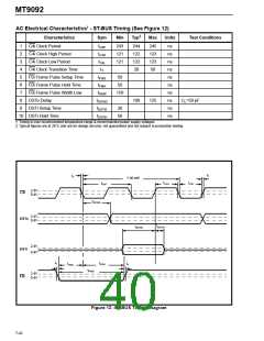
AC Electrical Characteristics† - ST-BUS Timing (See Figure 12)
‡
Characteristics
C4i Clock Period
Sym
Min
Typ
Max
Units
Test Conditions
1
2
3
4
5
6
7
8
9
tC4P
tC4H
243
121
121
244
122
122
20
245
123
123
50
ns
ns
ns
ns
ns
ns
ns
ns
ns
ns
C4i Clock High Period
C4i Clock Low Period
C4i Clock Transition Time
F0i Frame Pulse Setup Time
F0i Frame Pulse Hold Time
F0i Frame Pulse Width Low
DSTo Delay
tC4L
tT
tF0iS
tF0iH
tF0iW
tDSToD
tDSTiS
tDSTiH
50
50
150
100
125
CL=50 pF
DSTi Setup Time
30
50
10 DSTi Hold Time
† Timing is over recommended temperature range & recommended power supply voltages.
‡ Typical figures are at 25°C and are for design aid only: not guaranteed and not subject to production testing.
tT
tT
1 bit cell
tC4H
tC4L
tC4P
2.4V
C4i
0.4V
tDSToD
2.4V
0.4V
DSTo
tDSTiH
tDSTiS
2.4V
0.4V
DSTi
tT
tF0iH
tF0iS
tT
tF0iW
2.4V
0.4V
F0i
Figure 12 -ST-BUS Timing Diagram
7-42

 MITEL [ MITEL NETWORKS CORPORATION ]