MT9092
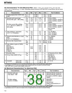
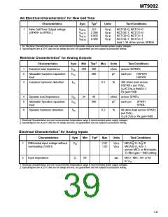
AC Electrical Characteristics† for New Call Tone
‡
Characteristics
Sym
Typ
Units
Test Conditions
1
New Call Tone Output voltage
(SPKR+ to SPKR-)
VNCT1
VNCT2
VNCT3
VNCT4
6.0
Vp-p
Vp-p
Vp-p
Vp-p
NCTG0=0, NCTG1=0
NCTG0=1, NCTG1=0
NCTG0=0, NCTG1=1
NCTG0=1, NCTG1=1
load > 34 ohms across SPKR±
2.390
0.950
0.380
† AC Electrical Characteristics are over recommended temperature range & recommended power supply voltages.
‡ Typical figures are at 25°C and are for design aid only: not guaranteed and not subject to production testing.
Electrical Characteristics† for Analog Outputs
‡
Characteristics
Sym
Min
Typ
Max
Units
Test Conditions
1
2
Earpiece load impedance
EZL
ECL
260
300
300
ohms across HSPKR±
Allowable Earpiece capacitive
load
pF
%
each pin:
HSPKR+
HSPKR-
3
Earpiece harmonic distortion
Speaker load impedance
ED
0.5
300 ohms load across
HSPKR± (tol-15%),
V ≤6.2Vp-p,RxA/u=1,
o
Rx gain=0dB
4
5
SZL
SCL
34
40
ohms across SPKR±
Allowable Speaker capacitive
load
300
pF
each pin
SPKR+
SPKR-
6
Speaker harmonic distortion
SD
0.5
%
40 ohms load across SPKR±
(tol-15%),
VO≤6.2Vp-p, Rx gain=0dB
† Electrical Characteristics are over recommended temperature range & recommended power supply voltages.
‡ Typical figures are at 25°C and are for design aid only: not guaranteed and not subject to production testing.
Electrical Characteristics† for Analog Inputs
‡
Characteristics
Sym
Min
Typ
Max
Units
Test Conditions
MICA/u=0, A/u=0
1
Differential input voltage without
overloading CODEC
VID
2.87
1.02
Vp-p
Vp-p
MICA/u=0, A/u=1
across MIC± or M± inputs,
Tx filter gain = 0dB setting
2
Input impedance
ZI
50
kΩ
MIC+, MIC-, M+ or M-
to VSS
.
† Electrical Characteristics are over recommended temperature range & recommended power supply voltages.
‡ Typical figures are at 25°C and are for design aid only: not guaranteed and not subject to production testing.
7-41

 MITEL [ MITEL NETWORKS CORPORATION ]