Preliminary Information
MT9076
Bit
Name
Functional Description
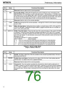
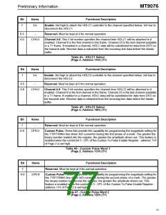
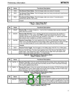
7
En
Enable. Set high to attach the HDLC1 controller to the channel specified below. Set low to
disconnect the HDLC1.
6-5
4-0
--
Reserved. Must be kept at 0 for normal operation.
CH4-0
Channel 4-0. This 5 bit number specifies the channel time HDLC1 will be attached to if
enabled. Channel 0 is the first channel in the frame. Channel 23 is the last channel available
in a T1 frame. If enabled in a channel, HDLC data will be substituted for data from DSTi on
the transmit side. Receive data is extracted from the incoming line data before the elastic
buffer.
Table 44 - HDLC1 Select
(Page 2, Address 1AH) (T1)
Bit
Name
Functional Description
7
En
Enable. Set high to attach the HDLC2 controller to the channel specified below. Set low to
disconnect the HDLC2.
6-5
4-0
- -
Reserved. Must be kept at 0 for normal operation.
CH4-0
Channel 4-0. This 5 bit number specifies the channel time HDLC2 will be attached to if
enabled. Channel 0 is the first channel in the frame. Channel 23 is the last channel available
in a T1 frame. If enabled in a channel, HDLC data will be substituted for data from DSTi on
the transmit side. Receive data is extracted from the incoming line data before the elastic
buffer.
Table 45 - HDLC2 Select
(Page 2, Address 1BH) (T1)
Bit
Name
Functional Description
7
- -
Reserved. Must be kept at 0 for normal operation.
6-0
CP6-0
Custom Pulse. These bits provide the capability for programming the magnitude setting for
the TTIP/TRING line driver A/D converter during the first phase of a mark. The greater the
binary number loaded into the register, the greater the amplitude driven out. This feature is
enabled when the control bit 3 - CPL of the Custom Tx Pulse Enable Register - address 11H
of Page 2 is set high.
Table 46 - Custom Pulse Word 1
(Page 2, Address 1CH) (T1)
Bit
Name
Functional Description
7
-
Reserved. Must be kept at 0 for normal operation.
6-0
CP6-0
Custom Pulse. These bits provide the capability for programming the magnitude setting for
the TTIP/TRING line driver A/D converter during the second phase of a mark. The greater
the binary number loaded into the register, the greater the amplitude driven out. This
feature is enabled when the control bit 3 - CPL of the Custom Tx Pulse Enable Register -
address 11H of Page 2 is set high.
Table 47 - Custom Pulse Word 2
(Page 2, Address 1DH) (T1)
73

 MITEL [ MITEL NETWORKS CORPORATION ]