MT9076
Preliminary Information
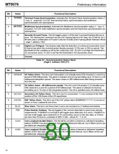
Bit
Name
Functional Description
Reserved. Must be kept at 0 for normal operation.
7-6
5
--
IMA
Inverse Mux Mode. Setting this bit high the I/O ports to allow for easy connection to the
Mitel MT90220. DSTi becomes a serial 1.544 data stream. C4b becomes a 1.544 MHz clock
that clocks DSTi in on the falling edge. RXFP becomes a positive framing pulse that is high
for the first bit (the framing bit) of the serial T1 stream coming from the pin DSto. This stream
is clocked out on the rising edge of Exclk. Set this pin low for all other applications.
4
3
--
Reserved. Must be set to 0 for normal operation.
G.802
G.802. Must be kept at 0 for normal operation. Set high for ST-BUS to DSI channel mapping
as per G.802.
2
8Men
8Mb/s Bit Rate Select. Setting this bit low enables a serial bit rate on DSTi, CSTi and DSTo,
CSTo of 2.048 Mb/s. Setting this bit high enables a gapped serial bit rate of 8.192 Mb/s on
DSTi, CSTi, DSTo and CSTo.
1-0
8MTS1-0 8 Mb/s Time Slot Select. These two bits select the active timeslots on the serial 8.192 Mb/
s channels. During the active timeslots incoming serial data on DSTi and CSTi is clocked
into the device, and data is clocked out onto DSTo and CSTo. During inactive timeslots DSTo
and CSTo are tristate. For all selections every fourth 8 Mb/s timeslot is active for the first 96
timeslots (24 x 8).
The timeslot selection (T1 mode) is as follows:
8MTS1 8MST0
Active timeslots
0 0
0 1
1 0
0,4,8,12,16,20,24,28,32,36,40,44,48,52,56,60,64,68,72,76,80,84,88,92
1,5,9,13,17,21,25,29,33,37,41,45,49,53,57,61,65,69,73,77,81,85,89,93
2,6,10,14,18,22,26,30,34,38,42,46,50,54,58,62,66,70,74,78,82,86,90,94
1 1 3,7,11,15,19,23,27,31,35,39,43,47,51,55,59,63,67,71,75,79,83,87,91,95
Table 42 - Serial Config. Word
(Page 2, Address 18H) (T1)
Bit
Name
Functional Description
7
En
Enable. Set high to attach the HDLC0 controller to the channel specified below. Set low to
disconnect the HDLC0.
6
FDLSEL
Facility Data Link Select. Set this bit to 0 to attach HDLC0 to the 4 kb/s facility data link.
Set this bit to 1 to attach HDLC0 to a payload timeslot.
5
--
Reserved. Must be kept at 0 for normal operation.
4-0
CH4-0
Channel 4-0. This 5 bit number specifies the channel time HDLC0 will be attached to if
enabled. Channel 0 is the first channel in the frame. Channel 23 is the last channel available
in a T1 frame. If enabled in a channel, HDLC data will be substituted for data from DSTi on
the transmit side. Receive data is extracted from the incoming line data before the elastic
buffer.
Table 43 - HDLC0 Select
(Page 2, Address 19H) (T1)
72

 MITEL [ MITEL NETWORKS CORPORATION ]