MT9076
Preliminary Information
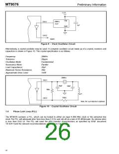
+3.3V
Vdd
20MHz
OUT
OSC1
OSC2
.1µF
GND
(open)
Figure 9 - Clock Oscillator Circuit
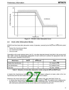
Alternatively, a crystal oscillator may be used. A complete oscillator circuit made up of a crystal, resistors and
capacitors is shown in Figure 10. The crystal specification is as follows.
Frequency:
20MHz
50ppm
Fundamental
Parallel
32pF
Tolerance:
Oscillation Mode:
Resonance Mode:
Load Capacitance:
Maximum Series Resistance:
Approximate Drive Level:
35Ω
1mW
20MHz
OSC1
56pF
39pF
1MΩ
1µH*
100Ω
OSC2
Note: the 1µH inductor is optional
Figure 10 - Crystal Oscillator Circuit
1.4
Phase Lock Loop (PLL)
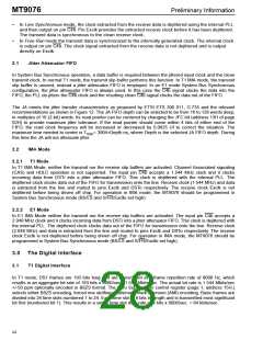
The MT9076 contains a PLL, which can be locked to either an input 4.096 Mhz clock or the extracted line
clock.The PLL will attenuate jitter from less than 2.5 Hz and roll-off at a rate of 20 dB/decade. Its intrinsic jitter
is less than 0.02 UI. The PLL will meet the jitter transfer characteristics as specified by AT&T document
TR 62411and the relevant recommendations as shown in Figure 12.
22

 MITEL [ MITEL NETWORKS CORPORATION ]