MT9076
Preliminary Information
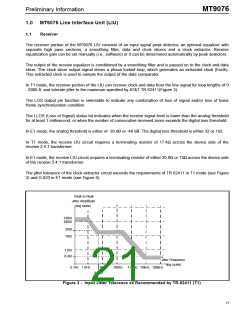
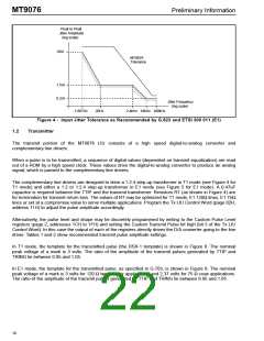
Peak to Peak
Jitter Amplitude
(log scale)
18UI
MT9076
Tolerance
1.5UI
0.2UI
Jitter Frequency
(log scale)
1.667Hz
20Hz
2.4kHz 18kHz 100kHz
Figure 4 - Input Jitter Tolerance as Recommended by G.823 and ETSI 300 011 (E1)
Transmitter
1.2
The transmit portion of the MT9076 LIU consists of a high speed digital-to-analog converter and
complementary line drivers.
When a pulse is to be transmitted, a sequence of digital values (dependent on transmit equalization) are read
out of a ROM by a high speed clock. These values drive the digital-to-analog converter to produce an analog
signal, which is passed to the complementary line drivers.
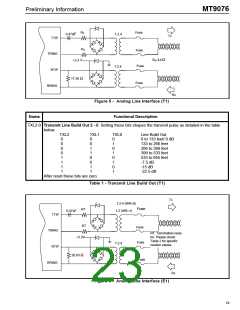
The complementary line drivers are designed to drive a 1:2.4 step-up transformer in T1 mode (see Figure 4 for
T1 mode) and either a 1:2 or 1:2.4 step-up transformer in E1 mode (see Figure 5 for E1 mode). A 0.47uF
capacitor is required between the TTIP and the transmit transformer. Resistors RT (as shown in Figure 4) are
for termination for transmit return loss. The values of RT may be optimized for T1 mode, E1 120Ω lines, E1 75Ω
lines or set at a compromise value to serve multiple applications. Program the Tx LIU Control Word (page 02H,
address 11H) to adjust the pulse amplitude accordingly.
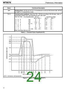
Alternatively, the pulse level and shape may be discretely programmed by writing to the Custom Pulse Level
registers (page 2, addresses 1CH to 1FH) and setting the Custom Transmit Pulse bit high (bit 3 of the Tx LIU
Control Word). In this case the output of each of the registers directly drives the D/A converter going to the line
driver. Tables 1 and 2 show recommended transmit pulse amplitude settings.
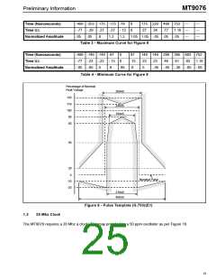
In T1 mode, the template for the transmitted pulse (the DSX-1 template) is shown in Figure 8. The nominal
peak voltage of a mark is 3 volts. The ratio of the amplitude of the transmit pulses generated by TTIP and
TRING lie between 0.95 and 1.05.
In E1 mode, the template for the transmitted pulse, as specified in G.703, is shown in Figure 8. The nominal
peak voltage of a mark is 3 volts for 120 Ω twisted pair applications and 2.37 volts for 75 Ω coax applications.
The ratio of the amplitude of the transmit pulses generated by TTIP and TRING lie between 0.95 and 1.05.
18

 MITEL [ MITEL NETWORKS CORPORATION ]