Preliminary Information
MT9075A
•
Alarm Indication Signal (AIS) - unframed all
ones signal for at least a double frame (512
bits) or two double frames (1024 bits);
Channel 16 Alarm Indication Signal - all ones
signal in channel 16;
12H) will go high. After the interrupt vector is read it
is automatically cleared and IRQ will return to a high
impedance state. The interrupt acknowledgment
function can also be accomplished by toggling the
INTA bit (page 01H, address 1AH).
•
•
•
Auxiliary pattern - 101010... pattern for at
least 512 bits;
All the interrupts of the MT9075A are maskable. This
is accomplished through the corresponding interrupt
mask words on page 01H (except for the HDLC
interrupt mask registers which are located on page
0BH and 0CH).
Loss of Signal - a loss of signal condition
occurs when the receive signal is detected
with more than 255 consecutive zeros. A
loss of signal condition will terminate when
an average ones density of at least 12.5%
has been received over a period of 255
contiguous pulse positions starting with a
pulse.
National Use Bit Interrupt Mask Word (address 19H)
Bit 7
Bit 0
•
•
Remote Signalling Multiframe Alarm - bit 6
(Y-bit) of the multiframe alignment signal.
T1 - (T1 timer bit on page 03H address 12H)
this status bit (and maskable interrupt) shall
be high when a signal that is not normal has
been received for a minimum of 100 msec.
This bit will be low when a normal signal is
being received.
T2 - (T2 timer bit on page 03H address 12H)
this status bit (and maskable interrupt) shall
be high when a normal signal has been
received for a minimum of 10 msec. This bit
will be low when an abnormal signal is being
received.
- - - PRBSO PRBS SanibI SabitI C8Sa6I Sa6I
Sa5I
Interrupt Mask Word Zero (address 1BH)
Bit 7
Bit 0
SYNI
RAII
AISI AISI6I LOSI FERI BPVO SLPI
Interrupt Mask Word One (address 1CH)
•
Bit 7
Bit 0
SIGI
EBI
CRCI CEFI
BPVI RCR1 RCR0 BERI
Interrupt Mask Word Two (address 1DH)
Bit 7
Bit 0
The alarm reporting latch (address 1BH page 04H)
contains a register whose bits are set high for
selected alarms. These bits stay high until the
register is read. This allows the controller to record
intermittent or sporadic alarm occurrences.
EBO CRCO CALNI FERO
JAI
BERO AUXPI CMFO
Interrupt Mask Word Three (address 1EH)
Bit 7
Bit 0
MFSYI CSYNI - - -
YI
1SEC
T1I
T2I
- - -
Automatic Alarms
HDLC Interrupt Masks (page 0BH&0CH, address 16H)
The signalling multiframe alarm can be made to
function automatically from control bit AUTY (page
01H, address 11H). When AUTY = 0 and signalling
multiframe alignment is not acquired (page 03H,
address 10H, bit 6, MFSYNC = 1), the MT9075A will
automatically transmit the multiframe alarm (Y-bit)
signal to the far end of the link. This transmission will
cease when signalling multiframe alignment is
acquired.
Bit 7
Bit 0
Ga
EOPD TEOP EopR
TxFl FATxU RxFf RxOv
After a device reset (RESET pin or RST control bit),
interrupts from the following interrupt mask words
are masked:
•
•
•
National use bit interrupt mask word
Interrupt mask words one through three.
HDLC interrupt mask word.
Interrupts
and the interrupts of mask word zero are unmasked.
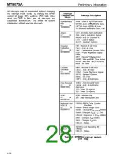
The MT9075A has an extensive suite of maskable
interrupts, which are divided into eight categories
based on the type of event that caused the interrupt.
Each interrupt category has an associated interrupt
vector described in Table 11. When unmasked
interrupts occur, IRQ will go low and one or more bits
of the interrupt vector IV7-IV0 (page 04H, address
4-155

 MITEL [ MITEL NETWORKS CORPORATION ]