MT9075A
Preliminary Information
Bit
Name
Functional Description
Bit
Name
Functional Description
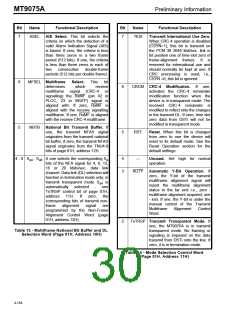
7
ASEL
AIS Select. This bit selects the
criteria on which the detection of a
valid Alarm Indication Signal (AIS)
is based. If zero, the criteria is less
than three zeros in a two frame
period (512 bits). If one, the criteria
is less than three zeros in each of
7
TIU0
Transmit International Use Zero.
When CRC-4 operation is disabled
(CSYN=1), this bit is transmit on
the PCM 30 2048 kbit/sec. link in
bit position one of time-slot zero of
frame-alignment frames. It is
reserved for international use and
should normally be kept at one. If
CRC processing is used, i.e.,
CSYN =0, this bit is ignored.
two
consecutive
double-frame
periods (512 bits per double-frame).
6
MFSEL Multiframe
Select.
This
bit
determines
which
receive
6
CRCM CRC-4 Modification. If one,
activates the CRC-4 remainder
modification function when the
device is in transparent mode. The
received CRC-4 remainder is
modified to reflect only the changes
in the transmit DL. If zero, time slot
zero data from DSTi will not be
modified in transparent mode.
multiframe signal (CRC-4 or
signalling) the RxMF (pin 42 in
PLCC, 23 in MQFP) signal is
aligned with. If zero, RxMF is
aligned with the receive signalling
multiframe. If one, RxMF is aligned
with the receive CRC-4 multiframe.
5
NBTB National Bit Transmit Buffer. If
one, the transmit NFAS signal
originates from the transmit national
bit buffer; if zero, the transmit NFAS
signal originates from the TNU4-8
bits of page 01H, address 12H.
5
RST
Reset. When this bit is changed
from zero to one the device will
reset to its default mode. See the
Reset Operation section for the
default settings.
4 - 0 S - S
A one selects the corresponding S
a
4
3
---
Unused. Set high for normal
operation.
a4
a8
bits of the NFA signal for 4, 8, 12,
16 or 20 kbits/sec. data link
channel. Data link (DL) selection will
function in termination mode only; in
AUTY Automatic Y-Bit Operation. If
zero, the Y-bit of the transmit
multiframe alignment signal will
report the multiframe alignment
status to the far end i.e., zero -
multiframe alignment acquired, one
- lost. If one, the Y-bit is under the
manual control of the Transmit
transmit transparent mode S
is
a4
automatically selected
TxTRSP control bit of page 01H,
address 11H. If zero, the
corresponding bits of transmit non-
frame alignment signal are
-
see
Multiframe
Word.
Alignment
Control
programmed by the Non-Frame
Alignment Control Word (page
01H, address 12H).
2
TxTRSP Transmit Transparent Mode. If
one, the MT9075A is in transmit
transparent mode. No framing or
signaling is imposed on the data
transmit from DSTi onto the line. If
zero, it is in termination mode.
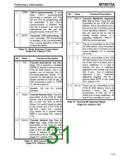
Table 13 - Multiframe National Bit Buffer and DL
Selection Word (Page 01H, Address 10H)
Table 14 - Mode Selection Control Word
(Page 01H, Address 11H)
4-158

 MITEL [ MITEL NETWORKS CORPORATION ]