ISO-CMOS MT8976
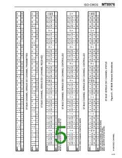
though the device only inserts the signalling
information in every 6th DS1 frame this information
must be input every ST-BUS frame.
†
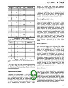
Frame #
FPS FDL CRC
Signalling
1
2
X
CB1
3
4
5
6
7
8
9
10
11
12
13
14
15
16
17
18
19
20
21
22
23
24
X
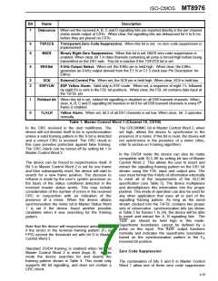
Robbed bit signalling can be disabled for all
channels on the DS1 link by bit 1 of Master Control
Word 1. It can also be disabled on a per channel
basis by bit 0 in the Per Channel Control Word 1.
0
X
CB2
X
A
B
C
D
0
X
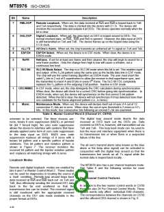
Operating Status Information
CB3
X
Status Information regarding the operation of the
device is output serially via the Control ST-BUS
output (CSTo). The CSTo serial stream contains
Master Status Words 1 and 2, 24 Per Channel Status
Words, and a Phase Status Word. The Master Status
Words contain all of the information needed to
determine the state of the interface and how well it is
operating. The information provided includes frame
and super frame synchronization, slip, bipolar
1
X
CB4
X
0
X
CB5
X
1
X
violation counter, alarms, CRC error count, F error
T
CB6
X
count, synchronization pattern mimic and a phase
status word. Tables 8 and 9 give a description of
each of the bits in Master Status Words 1 and 2, and
Table 10 gives a description of the Phase Status
Word.
1
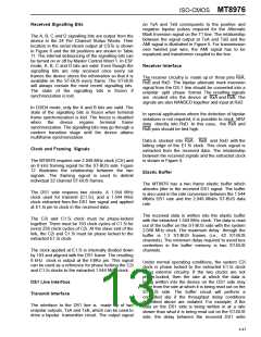
Table 3. ESF Frame Pattern
† These signalling bits are only valid if the robbed bit signalling is
active.
†
Frame #
FT
FS
Signalling
Alarm Detection
1
2
3
4
5
6
7
8
9
1
0
0
1
1
1
0
0
1
0
1
0
The device detects the yellow alarm for both D3/D4
frame format and ESF format. The D3/D4 yellow
alarm will be activated if a ‘0‘ is received in bit
position 2 of every DS0 channel for 600 msec. It will
be released in 200 msec after the contents of the bit
change. The alarm is detectable in the presence of
errors on the line. The ESF yellow alarm will become
active when the device has detected a string of eight
0’s followed by eight 1’s in the facility data link. It is
not detectable in the presence of errors on the line.
This means that the ESF yellow alarm will drop out
for relatively short periods of time, so the system will
have to integrate the ESF yellow alarm. The blue
alarm signal, in Master Status Word 2 , will also drop
out if there are errors on the line.
A
10
11
12
B
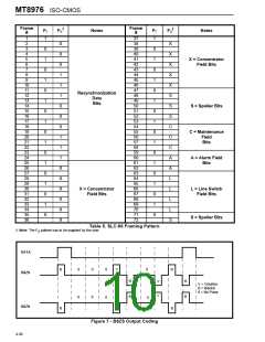
Table 4. D3/D4 Framer
† These signalling bits are only valid if the robbed bit signalling is
active.
Each control word has three bits that enable robbed
bit signalling, DS0 channel loopback and inversion of
the DS0 channel. A full description of each of the bits
is provided in Table 6.
Mimic Detection
The mimic bit in Master Status Word 1 will be set if,
during synchronization, a frame alignment pattern
Transmit Signalling Bits
(F or FPS bit pattern) was observed in more than
T
Control ST-BUS input number 1 (CSTi1) contains 24
additional per channel control words. These 24 ST-
BUS channels contain the A, B, C and D signalling
bits that the device uses at transmit time. The
position of these 24 per channel control words in the
ST-BUS is shown in Figure 6 and the position of the
ABCD signalling bits is shown in Table 7. Even
one position, i.e., if more than one candidate for the
frame synchronization position was observed. It will
be reset when the device resynchronizes. The mimic
bit, the terminal framing error bit and the CRC error
counter can be used separately or together to decide
if the receiver should be forced to reframe.
4-37

 MITEL [ MITEL NETWORKS CORPORATION ]