MT8976 ISO-CMOS
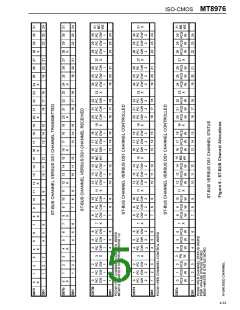
channel control words relate directly to the 24
information channels output on the DS1 side. The
master control words affect operation of the whole
device. Control ST-BUS input number 1 (CSTi1)
accepts an ST-BUS stream containing the A, B, C
and D signalling bits. The relationship between the
CSTi channels and the controlled DS0 channels is
shown in Figure 6. Status and signalling information
is received from the device via the control ST-BUS
output (CSTo). This serial output stream contains two
master status words, 24 per channel status words
and one Phase Status Word. Figure 6 shows the
correspondence between the received DS1 channels
and the status words. Detailed information on the
operation of the control interface is presented below.
Functional Description
The MT8976 provides a simple interface to a
bidirectional DS1 link. All of the formatting and
signalling insertion and detection is done by the
device. Various programmable options in the device
include: ESF, D3/D4, or SLC-96 mode, common
channel or robbed bit signalling, zero code
suppression, alarms, and local and remote loop
back. All data and control information is
communicated to the MT8976 via 2048 kbit/s serial
streams conforming to Mitel’s ST-BUS format.
The ST-BUS is a TDM serial bus that operates at
2048 kbits/s. The serial streams are divided into 125
µsec frames that are made up of 32 8 bit channels.
A serial stream that is made up of these 32 8 bit
channels is known as an ST-BUS stream, and one of
these 64 kbit/s channels is known as an ST-BUS
channel.
Programmable Features
The main features in the device are programmed
through two master control words which occupy
channels 15 and 31 in Control ST-BUS input stream
number 0 (CSTi0). These two eight bit words are
used to:
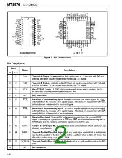
The system side of the MT8976 is made up of ST-
BUS inputs and outputs, i.e., control inputs and
outputs (CSTi/o) and data inputs and outputs
(DSTi/o). These signals are functionally represented
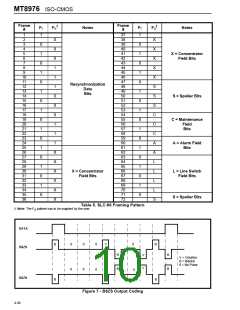
in Figure 3. The line side of the device is made up of
the split phase inputs and outputs that can be
interfaced to an external bipolar receiver and
transmitter. Functional transmit and receive timing
is shown in Figures 4 and 5.
•
•
Select the different operating modes of the
device ESF, D3/D4 or SLC-96.
Activate the features that are needed in a
certain application; common channel signalling,
zero code suppression, signalling debounce,
etc.
•
Turn on in service alarms, diagnostic loop
arounds, and the external control function.
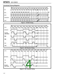
Data for transmission on the DS1 line is clocked
serially into the device at the DSTi pin. The DSTi pin
accepts a 32 channel time division multiplexed ST-
BUS stream. Data is clocked in with the falling edge
of the C2i clock. ST-BUS frame boundaries are
defined by the frame pulse applied at the F0i pin.
Only 24 of the available 32 channels on the ST-BUS
serial stream are actually transmitted on the DS1
side. The unused 8 channels are ignored by the
device.
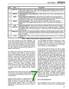
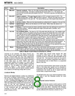
Tables 1 and 2 contain a complete explanation of the
function of the different bits in Master Control Words
1 and 2.
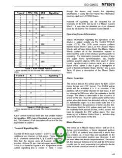
Major Operating Modes
The major operating modes of the device are
enabled by bits 2 and 4 of Master Control Word 2.
The Extended Superframe(ESF) mode is enabled
when bit 4 is set high. Bit 2 has no effect in this
mode. The ESF mode enables the transmission of
the S bit pattern shown in Table 3. This includes the
frame/superframe pattern, the CRC-6, and the
Facility Data Link (FDL). The device generates the
frame/multiframe pattern and calculates the CRC for
each superframe. The data clocked into the device
on the TxFDL pin is incorporated into the FDL. ESF
mode will also insert A, B, C and D signalling bits into
the 24 frame multiframe. The DS1 frame begins after
approximately 25 periods of the C1.5i clock from the
F0i frame pulse.
Data received from the DS1 line is clocked out of the
device in a similar manner at the DSTo pin. Data is
clocked out on the rising edge of the C2i clock. Only
24 of the 32 channels output by the device contain
the information from the DS1 line. The DSTo pin is,
however, actively driven during the unused channel
timeslots. Figure 6 shows the correspondence
between the DS1 channels and the ST-BUS
channels.
All control and monitoring of the device is
accomplished through two ST-BUS serial control
inputs and one serial control output. Control ST-BUS
input number 0 (CSTi0) accepts an ST-BUS serial
stream which contains the 24 per channel control
words and two master control words. The per
During synchronization the receiver locks to the
incoming frame, calculates the CRC and compares it
4-34

 MITEL [ MITEL NETWORKS CORPORATION ]