MT8976 ISO-CMOS
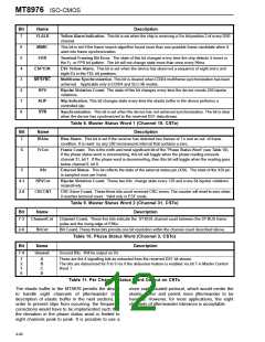
Bit
7
Name
Description
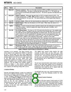
YLALR
Yellow Alarm Indication. This bit is set when the chip is receiving a 0 in bit position 2 of every DS0
channel.
6
5
4
3
2
1
0
MIMIC
ERR
This bit is set if the frame search algorithm found more than one possible frame candidate when it
went into frame synchronization.
Terminal Framing Bit Error. The state of this bit changes every time the chip detects 4 errors in
the F or FPS bit pattern. The bit will not change state more than once every 96ms.
T
ESFYLW
MFSYNC
BPV
ESF Yellow Alarm. This bit is set when the device has observed a sequence of eight one’s and
eight 0’s in the FDL bit positions.
Multiframe Synchronization. This bit is cleared when D3/D4 multiframe synchronization has been
achieved. Applicable only in D3/D4 and SLC-96 modes.
Bipolar Violation Count. The state of this bit changes every time the device counts 256 bipolar
violations.
SLIP
Slip Indication. This bit changes state every time the elastic buffer in the device performs a
controlled slip.
SYN
Synchronization. This bit is set when the device has not achieved synchronization. The bit is clear
when the device has synchronized to the received DS1 data stream.
Table 8. Master Status Word 1 (Channel 15, CSTo)
Description
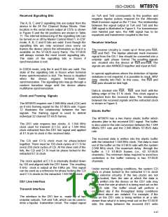
Bit
7
Name
BlAlm
Blue Alarm. This bit is set if the receiver has detected two frames of 1’s and an out of frame
condition. It is reset by any 250 microsecond interval that contains a zero.
6
FrCnt
Frame Count. This is the ninth and most significant bit of the “Phase Status Word“ (see Table 10).
If the phase status word is incrementing, this bit will toggle when the phase reading exceeds
channel 31, bit 7. If the phase word is decrementing, then this bit will toggle when the reading goes
below channel 0, bit 0.
5
XSt
External Status. This bit reflects the state of the external status pin (XSt). The state of the XSt pin
is sampled once per frame.
4-3
2-0
BPVCnt
CRCCNT
Bipolar Violation Count. These two bits change state every 128 and every 64 bipolar violations
respectively.
CRC Error Count. These three bits count received CRC errors. The counter will reset to zero when
it reaches terminal count. Valid only in ESF mode.
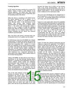
Table 9. Master Status Word 2 (Channel 31, CSTo)
Description
Bit
7-3
Name
ChannelCnt
Channel Count. These five bits indicate the ST-BUS channel count between the ST-BUS frame
pulse and the rising edge of E8Ko.
2-0
BitCnt
Bit Count. These three bits provide one bit resolution within the channel count described above.
Table 10. Phase Status Word (Channel 3, CSTo)
Bit
7-4
Name
Description
Unused
Unused Bits. Will be output as 0’s.
3
2
1
0
A
B
C
D
These are the 4 signalling bits as extracted from the received DS1 bit stream.
The bits are debounced for 6 to 9 ms if the debounce feature is enabled via bit 7 in Master Control
Word 1.
Table 11. Per Channel Status Word Output on CSTo
The elastic buffer in the MT8976 permits the device
to handle eight channels of jitter/wander (see
description of elastic buffer in the next section). In
order to prevent slips from occurring, the frequency
corrections would have to be implemented such that
the deviation in the phase status word is limited to
eight channels peak to peak. It is possible to use a
more sophisticated protocol, which would center the
elastic buffer and permit more jitter/wander to be
handled. However, for most applications, the eight
channels of jitter/wander tolerance is acceptable.
4-40

 MITEL [ MITEL NETWORKS CORPORATION ]