MT8976 ISO-CMOS
.
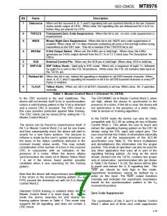
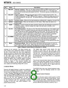
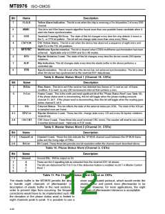
Bit
7
Name
Description
RMLOOP
Remote Loopback. When set, the data received at RxA and RxB is looped back to TxB
and TxA respectively. The data is clocked into the device with E1.5i. The device still
monitors the received data and outputs it at DSTo. The device operates normally when the
bit is clear.
6
DGLOOP
Digital Loopback. When set, the data input on DSTi is looped around to DSTo. The
normal received data on RxA, RxB and RxD is ignored. However, the data input at DSTi
is still transmitted on TxA and TxB. The device frames up on the looped data using the
C1.5i clock.
5
4
ALL1'S
ESF/D4
All One’s Alarm. When set, the chip transmits an unframed all 1's signal on TxA and TxB.
ESF/D4 Select. When set, the device is in ESF mode. When clear, the device is in
D3/D4 mode.
3
2
ReFR
Reframe. If set for at least one frame and then cleared, the chip will begin to search for a
new frame position. Only the change from high to low will cause a reframe, not a
continuous low level.
SLC-96
SLC-96 Mode Select. The chip is in SLC-96 mode when this bit is set. This enables input
and output of the FS bit pattern using the same pins as the facility data link in ESF mode.
The chip will use the same framing algorithm as D3/D4 mode. The user must insert the
valid FS bits in 2 out of 6 superframes to allow the receiver to find superframe sync, and
th
the transmitter to insert A and B bits in every 6 frame. The SLC-96 FDL completely
replaces the FS pattern in the outgoing S bit position. Inactive in ESF mode.
1
0
CRC/MIMIC In ESF mode, when set, the chip disregards the CRC calculation during synchronization.
When clear, the device will check for a correct CRC before going into synchronization. In
D3/D4 mode, when set, the device will synchronize on the first correct S-bit pattern
detected. When this bit is clear, the device will not synchronize if it has detected more than
one candidate for the frame alignment pattern (i.e., a mimic).
Maint.
Maintenance Mode. When set, the device will declare itself out-of-sync if 4 out of 12
consecutive FT bits are in error. When clear, the out-of-sync threshold is 2 errors in 4 FT
bits. In this mode, four consecutive bits following an errored FT bit are examined.
Table 2. Master Control Word 2 (Channel 31, CSTi0)
The digital loop around mode diverts the data
received at DSTi back out the DSTo pin. Data
received on DSTi is, however, still transmitted out via
TxA and TxB. This loop back mode can be used to
test the near end interface equipment when there is
no transmission line or when there is a suspected
failure of the line.
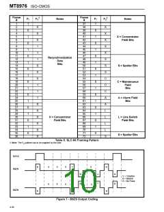
schemes to be selected. The three choices are:
none, binary 8 zero suppression (B8ZS), or jammed
bit (bit 7 forced high). No zero code suppression
allows the device to interface with systems that have
already applied some form of zero code suppression
to the data input on DSTi. B8ZS zero code
suppression replaces all strings of 8 zeros with a
known bit pattern and a specific pattern of bipolar
violations. This bit pattern and violation pattern is
shown in Figure 7. The receiver monitors the
received bit pattern and the bipolar violation pattern
and replaces all matching strings with 8 zeros.
The all one’s transmit alarm (also known as the blue
alarm or the keep alive signal) can be activated in
conjunction with the digital loop around so that the
transmission line sends an all 1's signal while the
normal data is looped back locally.
Loopback Modes
The MT8976 also has a per channel loopback mode.
See Table 6 and the following section for more
information.
Remote and digital loopback modes are enabled by
bits 6 and 7 in Master Control Word 2. These modes
can be used for diagnostics in locating the source of
a fault condition. Remote loop around loops back
data received at RxA and RxB back out on TxA and
TxB, thus effectively sending the received DS1 data
back to the far end unaltered so that the
transmission line can be tested. The received signal
is still monitored with the appropriate received
channels on the DS1 side made available in the
proper format at DSTo.
Per Channel Control Features
In addition to the two master control words in CSTi0
there are also 24 Per Channel Control Words. These
control words only affect individual DS0 channels.
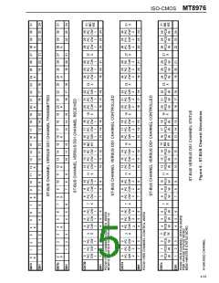
The correspondence between the channels on CSTi0
and the affected DS0 channel is shown in Fig. 6.
4-36

 MITEL [ MITEL NETWORKS CORPORATION ]