Preliminary Information
MH89760B
50
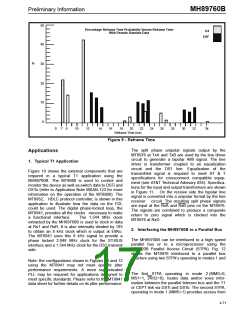
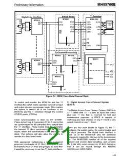
Percentage Reframe Time Probability Versus Reframe Time
With Pseudo Random Data
D4
ESF
40
%
30
20
10
0
0
7
8
10
12
14
16
18
20
22
24
26
28
30
32
34
Reframe Time (ms)
Figure 9 - Reframe Time
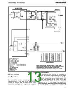
The split phase unipolar signals output by the
MT8976 at TxA and TxB are used by the line driver
circuit to generate a bipolar AMI signal. The line
driver is transformer coupled to an equalization
circuit and the DS1 line. Equalization of the
transmitted signal is required to meet AT & T
specifications for crossconnect compatible equip-
ment (see AT&T Technical Advisory #34). Specifica-
tions for the input and output transformers are shown
in Figure 11. On the receive side the bipolar line
signal is converted into a unipolar format by the line
receiver circuit. The resulting split phase signals
are input at the RxA and RxB pins on the MT8976.
The signals are combined to produce a composite
return to zero signal which is clocked into the
MT8976 at RxD.
Applications
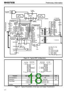
1. Typical T1 Application
Figure 10 shows the external components that are
required in a typical T1 application using the
MH89760B. The MT8980 is used to control and
monitor the device as well as switch data to DSTi and
DSTo (refer to Application Note MSAN-123 for more
information on the operation of the MT8980). The
MT8952, HDLC protocol controller, is shown in this
application to illustrate how the data on the FDL
could be used. The digital phase-locked loop, the
MT8941, provides all the clocks necessary to make
a functional interface.
The 1.544 MHz clock
extracted by the MH89760B is used to clock in data
at RxT and RxR. It is also internally divided by 193
to obtain an 8 kHz clock which is output at E8Ko.
The MT8941 uses this 8 kHz signal to provide a
phase locked 2.048 MHz clock for the ST-BUS
interface and a 1.544 MHz clock for the DS1 transmit
side.
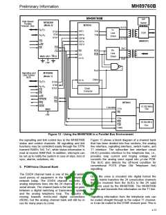
2. Interfacing the MH89760B to a Parallel Bus
The MH89760B can be interfaced to a high speed
parallel bus or to a microprocessor using the
MT8920B Parallel Access Circuit (STPA). Fig. 12
shows the MT8976 interfaced to a parallel bus
structure using two STPA‘s operating in modes 1 and
2.
Note: the configurations shown in Figures 10 and 12
using the MT8941 may not meet specific jitter
performance requirements. A more sophisticated
PLL may be required for applications designed to
meet specific standards. Please refer to the MT8941
data sheet for further details on its jitter performance.
The first STPA operating in mode 2 (MMS=0,
MS1=1, 24/32=0), routes data and/or voice infor-
mation between the parallel telecom bus and the T1
or CEPT link via DSTi and DSTo. The second STPA,
operating in mode 1 (MMS=1) provides access from
4-71

 MITEL [ MITEL NETWORKS CORPORATION ]