CCU 3000, CCU 3000-I
CCU 3001, CCU 3001-I
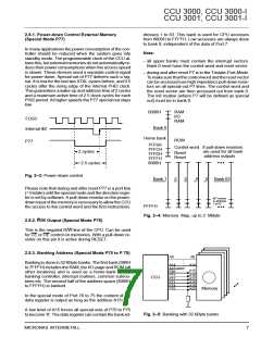
2.9. Reset Function
dictated by reset. The switches have the following func-
tions:
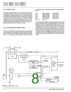
The internal reset provides a correct basic setup of the
complete hardware on the chip. For this the internal con-
trol register is loaded during reset. One reserved byte in
the ROM is accessed by the reset circuit and its content
is copied into the control register. The internal voltage
supervision resets the IC if the voltage is too low. The re-
set pin is also used as output for internal reset sources
(watchdog, power-down detector, clock supervisor). In-
ternal resistors limit the maximum current.
bit 0
bit 1
bit 2
bit 3
bit 4
bit 5 to 7
CPU_disable
RAM_disable
ROM_disable
R/W-mode P4
Bus external
set to 1
(low active)
(low active)
(low active)
(low active)
(low active)
The setting at the R/W-pin decides whether the control
word is read internally or externally. Bit 0 to bit 2 are the
switches which can disable RAM, ROM and CPU. For
external access a pull-up resistor must be connected to
the R/W pin (CCU 3001). Bit 4 switches P1, P2 and P3
into the system bus mode. If the internal CPU is active,
the direction of the data bus drivers is automatically set
correctly, sothatnoadditionaldecodingisnecessary. Bit
3 switches P4 into the R/W mode. If no external write ac-
cess is necessary, (ext. EPROM), P4 can stay in the port
mode.
2.10. Control Register (address 201H)
This is a combination of control switches in an 8-bit reg-
ister. During reset it is loaded with the contents of the ad-
dress FFF9H, but it can also be read and written via soft-
ware. The controller starts operation with the setting
C =
1
C =
22 p
X1
22 p
2
X2
CCU 3000, CCU 3001
Prescaler
Φ2
OSC
D ...D
0
7
CLKRES
Supervision
Clock
Reset +
Control–
word
A ...A
0
15
Internal
Reset
POR
Logic
Voltage
Detector
V
SUP
300 k
RESOUT
RESIN
RES
DOGBIT
RESET
Watchdog
Fig. 2–6: Oscillator and reset
8
MICRONAS INTERMETALL

 MICRONAS [ MICRONAS ]