CCU 3000, CCU 3000-I
CCU 3001, CCU 3001-I
Contents
Page
Section
Title
4
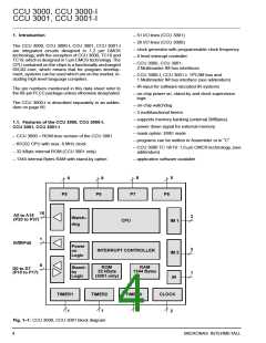
1.
Introduction
4
1.1.
Features of the CCU 3000, CCU 3000-I, CCU 3001, CCU 3001-I
5
2.
Functional Description
5
2.1.
ROM
5
2.2.
RAM
5
2.3.
CPU
5
2.4.
Clock Generator
5
2.5.
PORT 1 to PORT 3, PORT 6 to PORT 8
PORT 4
5
2.6.
5
2.7.
I/O-Lines P50 to P55
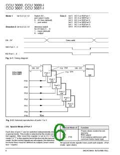
Special Mode of Port 7
Power-down Control External Memory (Special Mode P77)
R/W Output (Special Mode P76)
Banking Address (Special Mode P70 to P75)
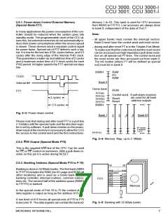
Reset Function
6
2.8.
7
2.8.1.
2.8.2.
2.8.3.
2.9.
7
7
8
8
2.10.
2.11.
2.12.
2.13.
2.14.
2.15.
2.16.
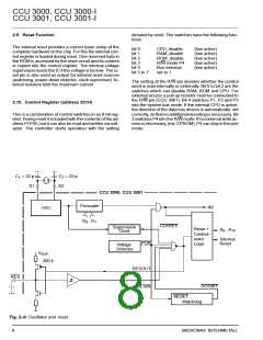
Control Register
10
12
14
19
21
21
Interrupt Controller
IM Bus Interface
Multifunctional Timer
Watchdog
IR-Input
Mask Options
22
22
22
22
3.
Definitions
3.1.
3.2.
3.3.
Interrupt Definitions
Memory Mappings
I/O Definitions
23
23
24
25
28
31
32
32
32
32
33
34
34
36
36
37
38
4.
Specifications
4.1.
Outline Dimensions
4.2.
Pin Configuration
4.3.
Pin Connections and Short Descriptions
Pin Descriptions
4.4.
4.5.
Pin Circuits
4.6.
Electrical Characteristics
Absolute Maximum Ratings
Recommended Operating Conditions
Recommended Crystal Characteristics
DC Characteristics
4.6.1.
4.6.2.
4.6.3.
4.6.4.
4.6.5.
4.6.6.
4.6.7.
4.6.8.
4.6.9.
4.6.10.
Using External Devices
AC Characteristics
IM Bus Waveforms
Description of the IM Bus
Recommended Operating Conditions of IM Bus
Registers
59
61
62
5.
6.
7.
Index
Addendum: CCU 3000, CCU 3000-I EMU Versions
Addendum: CCU 3000 1 µm Version
2
MICRONAS INTERMETALL

 MICRONAS [ MICRONAS ]