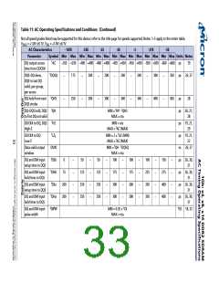
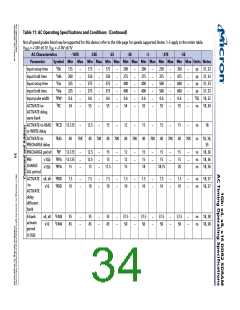
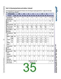
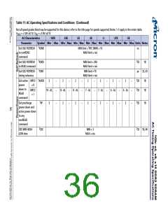
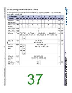
Table 11: AC Operating Specifications and Conditions (Continued)
Not all speed grades listed may be supported for this device; refer to the title page for speeds supported; Notes: 1–5 apply to the entire table;
VDDQ = +1.8V ±0.1V, VDD = +1.8V ±0.1V
AC Characteristics
-187E
-25E
-25
-3E
-3
-37E
-5E
Parameter
Symbol Min Max Min Max Min Max Min Max Min Max Min Max Min Max Units Notes
DQ output access
time from CK/CK#
tAC
–350 +350 –400 +400 –400 +400 –450 +450 –450 +450 –500 +500 –600 +600
ps
ps
19
DQS–DQ skew,
DQS to last DQ
valid, per group,
per access
tDQSQ
175
200
200
240
240
300
350
26, 27
–
–
–
–
–
–
–
DQ hold from next
DQS strobe
tQHS
tQH
250
300
300
340
340
400
450
ps
ps
ps
ps
ns
ps
ps
ps
ps
28
–
–
–
–
–
–
–
DQ–DQS hold, DQS
to first DQ not valid
MIN = tHP - tQHS
MAX = n/a
26, 27,
28
CK/CK# to DQ, DQS
High-Z
tHZ
MIN = n/a
19, 21,
29
MAX = tAC (MAX)
MIN = 2 × tAC (MIN)
MAX = tAC (MAX)
MIN = tQH - tDQSQ
MAX = n/a
CK/CK# to DQ
Low-Z
tLZ2
19, 21,
22
Data valid output
window
DVW
tDSb
tDHb
tDSa
tDHa
tDIPW
26, 27
DQ and DM input
setup time to DQS
0
50
50
100
100
175
300
300
100
225
350
350
150
275
400
400
26, 30,
31
–
–
–
–
–
–
–
–
–
–
–
–
–
–
–
–
–
–
–
–
–
–
–
–
–
–
–
–
DQ and DM input
hold time to DQS
75
125
250
250
125
250
250
175
300
300
26, 30,
31
DQ and DM input
setup time to DQS
200
200
26, 30,
31
DQ and DM input
hold time to DQS
26, 30,
31
DQ and DM input
pulse width
MIN = 0.35 × tCK
MAX = n/a
tCK 18, 32

 MICRON [ MICRON TECHNOLOGY ]