P33-65nm
• Figure 21, “Continuous Burst Read, showing an Output Delay Timing” on page 53
• Figure 22, “Synchronous Burst-Mode Four-Word Read Timing” on page 54
7.3
Read Device Identifier
The Read Device Identifier command instructs the device to output manufacturer code,
device identifier code, block-lock status, OTP register data, or configuration register
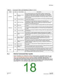
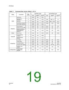
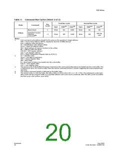
data (see Section 6.2, “Device Command Bus Cycles” on page 18 for details on issuing
the Read Device Identifier command). Table 8, “Device Identifier Information” on
page 22 and Table 9, “Device ID codes” on page 22 show the address offsets and data
values for this device.
Table 8:
Device Identifier Information
(1,2)
Item
Address
Data
Manufacturer Code
0x00
0x01
0x89h
ID (see Table 9)
Lock Bit:
Device ID Code
Block Lock Configuration:
• Block Is Unlocked
DQ0 = 0b0
• Block Is Locked
BBA + 0x02
DQ0 = 0b1
• Block Is not Locked-Down
• Block Is Locked-Down
Read Configuration Register
DQ1 = 0b0
DQ1 = 0b1
0x05
DBA + 0x07
0x80
RCR Contents
(3)
General Purpose Register
Lock Register 0
general data
PR-LK0
64-bit Factory-Programmed OTP register
64-bit User-Programmable OTP Register
Lock Register 1
0x81–0x84
0x85–0x88
0x89
Factory OTP register data
User OTP register data
OTP register lock data
User OTP register data
128-bit User-Programmable OTP registers
Notes:
0x8A–0x109
1.
2.
3.
BBA = Block Base Address.
DBA = Device base Address, Numonyx reserves other configuration address locations
In P33-65nm, the GPR is used as read out register for Extended Functional interface command.
Table 9:
Device ID codes
Device Identifier Codes
ID Code Type
Device Density
–T
–B
(Top Parameter)
(Bottom Parameter)
Device Code
256-Mbit
891F
8922
Note: The 512-Mbit devices do not have a Device ID associated with them. Each die within the stack can be identified by either
of the 256-Mbit Device ID codes depending on its parameter option.
7.4
Read CFI
The Read CFI command instructs the device to output Common Flash Interface data
when read.
Datasheet
22
Aug 2009
Order Number: 320003-08

 MICRON [ MICRON TECHNOLOGY ]