P33-65nm
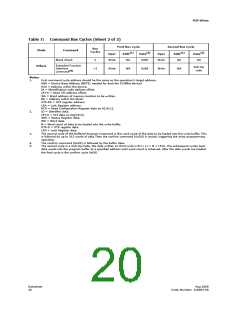
to issue 70h to read SR data after E8h command otherwise 70h would be counted as
Word Count.
On the next write, a word count is written to the device at the buffer address. This tells
the device how many data words will be written to the buffer, up to the maximum size
of the buffer.
On the next write, a device start address is given along with the first data to be written
to the flash memory array. Subsequent writes provide additional device addresses and
data. All data addresses must lie within the start address plus the word count.
Optimum programming performance and lower power usage are obtained by aligning
the starting address at the beginning of a 512-word boundary (A[9:1] = 0x00). The
maximum buffer size would be 256-word if the misaligned address range is crossing a
512-word boundary during programming.
After the last data is written to the buffer, the Buffered Programming Confirm command
must be issued to the original block address. The WSM begins to program buffer
contents to the flash memory array. If a command other than the Buffered
Programming Confirm command is written to the device, a command sequence error
occurs and SR[7,5,4] are set. If an error occurs while writing to the array, the device
stops programming, and SR[7,4] are set, indicating a programming failure.
When Buffered Programming has completed, additional buffer writes can be initiated by
issuing another Buffered Programming Setup command and repeating the buffered
program sequence. Buffered programming may be performed with VPP = VPPL or VPPH
(see Section 13.2, “Operating Conditions” on page 45 for limitations when operating
the device with VPP = VPPH).
If an attempt is made to program past an erase-block boundary using the Buffered
Program command, the device aborts the operation. This generates a command
sequence error, and SR[5,4] are set.
If Buffered programming is attempted while VPP is below VPPLK, SR[4,3] are set. If any
errors are detected that have set Status Register bits, the Status Register should be
cleared using the Clear Status Register command.
8.3
Buffered Enhanced Factory Programming
Buffered Enhanced Factory Programing (BEFP) speeds up Multi-Level Cell (MLC) flash
programming. The enhanced programming algorithm used in BEFP eliminates
traditional programming elements that drive up overhead in device programmer
systems. (see Figure 34, “BEFP Flowchart” on page 75).
BEFP consists of three phases: Setup, Program/Verify, and Exit It uses a write buffer to
spread MLC program performance across 512 data words. Verification occurs in the
same phase as programming to accurately program the flash memory cell to the
correct bit state.
A single two-cycle command sequence programs the entire block of data. This
enhancement eliminates three write cycles per buffer: two commands and the word
count for each set of 512 data words. Host programmer bus cycles fill the device’s write
buffer followed by a status check. SR.0 indicates when data from the buffer has been
programmed into sequential flash memory array locations.
Following the buffer-to-flash array programming sequence, the Write State Machine
(WSM) increments internal addressing to automatically select the next 512-word array
boundary. This aspect of BEFP saves host programming equipment the address-bus
setup overhead.
Datasheet
24
Aug 2009
Order Number: 320003-08

 MICRON [ MICRON TECHNOLOGY ]