PIC24FJ64GA104 FAMILY
24.1 Measuring Capacitance
24.0 CHARGE TIME
MEASUREMENT UNIT (CTMU)
The CTMU module measures capacitance by generat-
ing an output pulse, with a width equal to the time
Note:
This data sheet summarizes the features
between edge events, on two separate input channels.
The pulse edge events to both input channels can be
selected from four sources: two internal peripheral
modules (OC1 and Timer1) and two external pins
(CTEDG1 and CTEDG2). This pulse is used with the
module’s precision current source to calculate
capacitance according to the relationship:
of this group of PIC24F devices. It is not
intended to be a comprehensive reference
source. For more information, refer to the
associated “PIC24F Family Reference
Manual”, Section 11. “Charge Time
Measurement Unit (CTMU)” (DS39724).
The Charge Time Measurement Unit is a flexible
analog module that provides accurate differential time
measurement between pulse sources, as well as
asynchronous pulse generation. Its key features
include:
dV
i = C •
dT
For capacitance measurements, the A/D Converter
samples an external capacitor (CAPP) on one of its
input channels after the CTMU output’s pulse. A Preci-
sion Resistor (RPR) provides current source calibration
on a second A/D channel. After the pulse ends, the
converter determines the voltage on the capacitor. The
actual calculation of capacitance is performed in
software by the application.
• Four edge input trigger sources
• Polarity control for each edge source
• Control of edge sequence
• Control of response to edges
• Time measurement resolution of 1 nanosecond
• Accurate current source suitable for capacitive
measurement
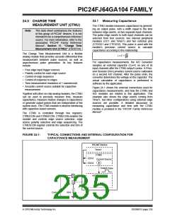
Figure 24-1 shows the external connections used for
capacitance measurements, and how the CTMU and
A/D modules are related in this application. This
example also shows the edge events coming from
Timer1, but other configurations using external edge
sources are possible. A detailed discussion on
measuring capacitance and time with the CTMU
module is provided in the “PIC24F Family Reference
Manual”.
Together with other on-chip analog modules, the CTMU
can be used to precisely measure time, measure
capacitance, measure relative changes in capacitance
or generate output pulses that are independent of the
system clock. The CTMU module is ideal for interfacing
with capacitive-based sensors.
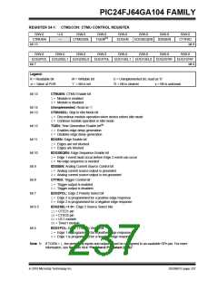
The CTMU is controlled through two registers:
CTMUCON and CTMUICON. CTMUCON enables the
module and controls edge source selection, edge
source polarity selection and edge sequencing. The
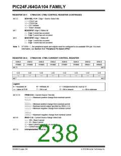
CTMUICON register controls the selection and trim of
the current source.
FIGURE 24-1:
TYPICAL CONNECTIONS AND INTERNAL CONFIGURATION FOR
CAPACITANCE MEASUREMENT
PIC24F Device
Timer1
CTMU
EDG1
EDG2
Current Source
Output
Pulse
A/D Converter
ANx
ANY
CAPP
RPR
2010 Microchip Technology Inc.
DS39951C-page 235

 MICROCHIP [ MICROCHIP ]