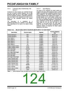
PIC24FJ64GA104 FAMILY
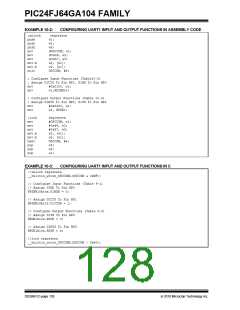
EXAMPLE 10-2:
CONFIGURING UART1 INPUT AND OUTPUT FUNCTIONS IN ASSEMBLY CODE
;unlock
push
push
push
mov
mov
mov
mov.b
mov.b
bclr
registers
w1;
w2;
w3;
#OSCCON, w1;
#0x46, w2;
#0x57, w3;
w2, [w1];
w3, [w1];
OSCCON, #6;
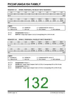
; Configure Input Functions (Table10-2)
; Assign U1CTS To Pin RP1, U1RX To Pin RP0
mov
mov
#0x0100, w1;
w1,RPINR18;
; Configure Output Functions (Table 10-3)
; Assign U1RTS To Pin RP3, U1TX To Pin RP2
mov
mov
#0x0403, w1;
w1, RPOR1;
;lock
mov
mov
registers
#OSCCON, w1;
#0x46, w2;
#0x57, w3;
w2, [w1];
w3, [w1];
OSCCON, #6;
w3;
mov
mov.b
mov.b
bset
pop
pop
w2;
pop
w1;
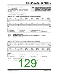
EXAMPLE 10-3:
CONFIGURING UART1 INPUT AND OUTPUT FUNCTIONS IN C
//unlock registers
__builtin_write_OSCCONL(OSCCON & 0xBF);
// Configure Input Functions (Table 9-1)
// Assign U1RX To Pin RP0
RPINR18bits.U1RXR = 0;
// Assign U1CTS To Pin RP1
RPINR18bits.U1CTSR = 1;
// Configure Output Functions (Table 9-2)
// Assign U1TX To Pin RP2
RPOR1bits.RP2R = 3;
// Assign U1RTS To Pin RP3
RPOR1bits.RP3R = 4;
//lock registers
__builtin_write_OSCCONL(OSCCON | 0x40);
DS39951C-page 128
2010 Microchip Technology Inc.

 MICROCHIP [ MICROCHIP ]