PIC18F2480/2580/4480/4580
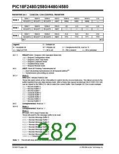
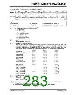
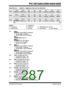
REGISTER 24-2: CANSTAT: CAN STATUS REGISTER
R-1
R-0
R-0
R-0
—
R-0
R-0
R-0
U-0
—
Mode 0
(1)
(1)
(1)
OPMODE2
OPMODE1
OPMODE0
ICODE3
ICODE2
ICODE1
R-1
R-0
R-0
R-0
R-0
R-0
R-0
R-0
Mode 1,2
(1)
(1)
(1)
OPMODE2
bit 7
OPMODE1
OPMODE0
EICODE4 EICODE3 EICODE2 EICODE1
EICODE0
bit 0
Legend:
R = Readable bit
-n = Value at POR
W = Writable bit
‘1’ = Bit is set
U = Unimplemented bit, read as ‘0’
‘0’ = Bit is cleared x = Bit is unknown
bit 7-5
OPMODE<2:0>: Operation Mode Status bits(1)
111= Reserved
110= Reserved
101= Reserved
100= Configuration mode
011= Listen Only mode
010= Loopback mode
001= Disable/Sleep mode
000= Normal mode
bit 4
Mode 0:
Unimplemented: Read as ‘0’
bit 3-1
ICODE<3:1>: Interrupt Code bits
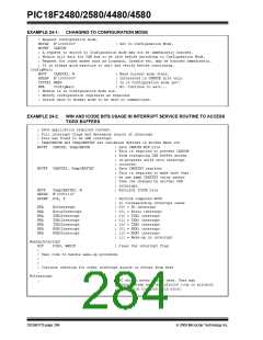
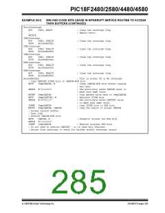
When an interrupt occurs, a prioritized coded interrupt value will be present in these bits. This code
indicates the source of the interrupt. By copying ICODE<3:1> to WIN<3:0> (Mode 0) or EICODE<4:0> to
EWIN<4:0> (Mode 1 and 2), it is possible to select the correct buffer to map into the Access Bank area.
See Example 24-2 for a code example. To simplify the description, the following table lists all five bits.
Mode 0
00000
00010
00100
00110
01000
01010
01100
00010
-----
-----
-----
-----
-----
-----
-----
-----
Mode 1
00000
00010
00100
00110
01000
10001
10000
01110
10000
10001
10010
10011
10100
10101
10110
10111
Mode 2
00000
00010
00100
00110
01000
-----
10000
01110
No interrupt
CAN bus error interrupt
TXB2 interrupt
TXB1 interrupt
TXB0 interrupt
RXB1 interrupt
RXB0 interrupt
Wake-up interrupt
RXB0 interrupt
RXB1 interrupt
RX/TX B0 interrupt
RX/TX B1 interrupt
RX/TX B2 interrupt
RX/TX B3 interrupt
RX/TX B4 interrupt
RX/TX B5 interrupt
10000
10000
10010(2)
10011(2)
10100(2)
10101(2)
10110(2)
10111(2)
bit 0
Unimplemented: Read as ‘0’
bit 4-0
Mode 1, 2:
EICODE<4:0>: Interrupt Code bits
See ICODE<3:1> above.
Note 1: To achieve maximum power saving and/or able to wake-up on CAN bus activity, switch CAN module in
Disable/Sleep mode before putting device to Sleep.
2: If buffer is configured as receiver, EICODE bits will contain ‘10000’ upon interrupt.
© 2009 Microchip Technology Inc.
DS39637D-page 283

 MICROCHIP [ MICROCHIP ]