PIC18F2480/2580/4480/4580
24.1 Module Overview
24.0 ECAN MODULE
The CAN bus module consists of a protocol engine and
message buffering and control. The CAN protocol
engine automatically handles all functions for receiving
and transmitting messages on the CAN bus. Messages
are transmitted by first loading the appropriate data
registers. Status and errors can be checked by reading
the appropriate registers. Any message detected on
the CAN bus is checked for errors and then matched
against filters to see if it should be received and stored
in one of the two receive registers.
PIC18F2480/2580/4480/4580 devices contain an
Enhanced Controller Area Network (ECAN) module.
The ECAN module is fully backward compatible with
the CAN module available in PIC18CXX8 and
PIC18FXX8 devices.
The Controller Area Network (CAN) module is a serial
interface which is useful for communicating with other
peripherals or microcontroller devices. This interface,
or protocol, was designed to allow communications
within noisy environments.
The CAN module supports the following frame types:
The ECAN module is a communication controller, imple-
menting the CAN 2.0A or B protocol as defined in the
BOSCH specification. The module will support CAN 1.2,
CAN 2.0A, CAN 2.0B Passive and CAN 2.0B Active
versions of the protocol. The module implementation is
a full CAN system; however, the CAN specification is not
covered within this data sheet. Refer to the BOSCH CAN
specification for further details.
• Standard Data Frame
• Extended Data Frame
• Remote Frame
• Error Frame
• Overload Frame Reception
The CAN module uses the RB2/CANTX and RB3/
CANRX pins to interface with the CAN bus. In normal
mode, the CAN module automatically overrides
TRISB<2>. The user must ensure that TRISB<3> is
set.
The module features are as follows:
• Implementation of the CAN protocol, CAN 1.2,
CAN 2.0A and CAN 2.0B
• DeviceNetTM data bytes filter support
• Standard and extended data frames
• 0-8 bytes data length
• Programmable bit rate up to 1 Mbit/sec
• Fully backward compatible with the PIC18XXX8
CAN module
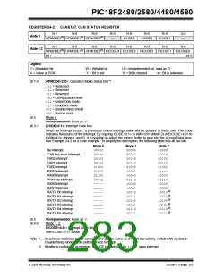
24.1.1
MODULE FUNCTIONALITY
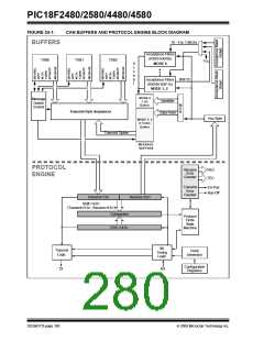
The CAN bus module consists of a protocol engine,
message buffering and control (see Figure 24-1). The
protocol engine can best be understood by defining the
types of data frames to be transmitted and received by
the module.
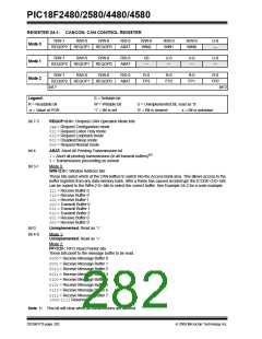
• Three modes of operation:
- Mode 0 – Legacy mode
- Mode 1 – Enhanced Legacy mode with
DeviceNet support
The following sequence illustrates the necessary initial-
ization steps before the ECAN module can be used to
transmit or receive a message. Steps can be added or
removed depending on the requirements of the
application.
- Mode 2 – FIFO mode with DeviceNet support
• Support for remote frames with automated handling
• Double-buffered receiver with two prioritized
received message storage buffers
• Six buffers programmable as RX and TX
message buffers
• 16 full (standard/extended identifier) acceptance
filters that can be linked to one of four masks
• Two full acceptance filter masks that can be
assigned to any filter
• One full acceptance filter that can be used as either
an acceptance filter or acceptance filter mask
• Three dedicated transmit buffers with application
specified prioritization and abort capability
• Programmable wake-up functionality with
integrated low-pass filter
1. Initial LAT and TRIS bits for RX and TX CAN.
2. Ensure that the ECAN module is in Configuration
mode.
3. Select ECAN Operational mode.
4. Set up the Baud Rate registers.
5. Set up the Filter and Mask registers.
6. Set the ECAN module to normal mode or any
other mode required by the application logic.
• Programmable Loopback mode supports self-test
operation
• Signaling via interrupt capabilities for all CAN
receiver and transmitter error states
• Programmable clock source
• Programmable link to timer module for
time-stamping and network synchronization
• Low-power Sleep mode
© 2009 Microchip Technology Inc.
DS39637D-page 279

 MICROCHIP [ MICROCHIP ]