PIC18F2480/2580/4480/4580
Once the TXREG register transfers the data to the TSR
19.2 EUSART Asynchronous Mode
register (occurs in one TCY), the TXREG register is empty
and the TXIF flag bit (PIR1<4>) is set. This interrupt can
be enabled or disabled by setting or clearing the interrupt
enable bit, TXIE (PIE1<4>). TXIF will be set regardless of
the state of TXIE; it cannot be cleared in software. TXIF
is also not cleared immediately upon loading TXREG, but
becomes valid in the second instruction cycle following
the load instruction. Polling TXIF immediately following a
load of TXREG will return invalid results.
The Asynchronous mode of operation is selected by
clearing the SYNC bit (TXSTA<4>). In this mode, the
EUSART uses standard Non-Return-to-Zero (NRZ)
format (one Start bit, eight or nine data bits and one Stop
bit). The most common data format is 8 bits. An on-chip
dedicated 8-bit/16-bit Baud Rate Generator can be used
to derive standard baud rate frequencies from the
oscillator.
The EUSART transmits and receives the LSb first. The
EUSART’s transmitter and receiver are functionally
independent but use the same data format and baud
rate. The Baud Rate Generator produces a clock, either
x16 or x64 of the bit shift rate depending on the BRGH
and BRG16 bits (TXSTA<2> and BAUDCON<3>). Parity
is not supported by the hardware, but can be
implemented in software and stored as the 9th data bit.
While TXIF indicates the status of the TXREG register,
another bit, TRMT (TXSTA<1>), shows the status of
the TSR register. TRMT is a read-only bit which is set
when the TSR register is empty. No interrupt logic is
tied to this bit so the user has to poll this bit in order to
determine if the TSR register is empty.
Note 1: The TSR register is not mapped in data
memory so it is not available to the user.
When operating in Asynchronous mode, the EUSART
module consists of the following important elements:
2: Flag bit, TXIF, is set when enable bit,
In Asynchronous mode, clock polarity is selected with
the TXCKP bit (BAUDCON<4>). Setting TXCKP sets
the Idle state on CK as high, while clearing the bit sets
the Idle state as low. Data polarity is selected with the
RXDTP bit (BAUDCON<5>).
TXEN, is set.
To set up an Asynchronous Transmission:
1. Initialize the SPBRGH:SPBRG registers for the
appropriate baud rate. Set or clear the BRGH
and BRG16 bits, as required, to achieve the
desired baud rate.
Setting RXDTP inverts data on RX, while clearing the
bit has no affect on received data.
2. Enable the asynchronous serial port by clearing
bit, SYNC, and setting bit, SPEN.
• Baud Rate Generator
• Sampling Circuit
3. If interrupts are desired, set enable bit, TXIE.
• Asynchronous Transmitter
• Asynchronous Receiver
4. If 9-bit transmission is desired, set transmit bit,
TX9. Can be used as address/data bit.
• Auto-Wake-up on Sync Break Character
• 12-Bit Break Character Transmit
• Auto-Baud Rate Detection
5. Enable the transmission by setting bit, TXEN,
which will also set bit, TXIF.
6. If 9-bit transmission is selected, the ninth bit
should be loaded in bit, TX9D.
19.2.1
EUSART ASYNCHRONOUS
TRANSMITTER
7. Load data to the TXREG register (starts
transmission).
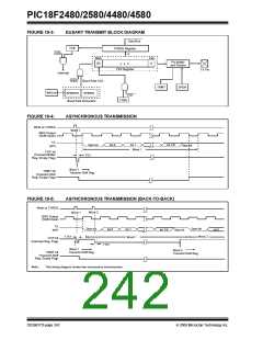
The EUSART transmitter block diagram is shown in
Figure 19-3. The heart of the transmitter is the Transmit
(Serial) Shift Register (TSR). The Shift register obtains
its data from the Read/Write Transmit Buffer register,
TXREG. The TXREG register is loaded with data in
software. The TSR register is not loaded until the Stop
bit has been transmitted from the previous load. As
soon as the Stop bit is transmitted, the TSR is loaded
with new data from the TXREG register (if available).
8. If using interrupts, ensure that the GIE and PEIE bits
in the INTCON register (INTCON<7:6>) are set.
© 2009 Microchip Technology Inc.
DS39637D-page 241

 MICROCHIP [ MICROCHIP ]