PIC18F2480/2580/4480/4580
19.1.3
AUTO-BAUD RATE DETECT
Note 1: If the WUE bit is set with the ABDEN bit,
Auto-Baud Rate Detection will occur on
the byte following the Break character.
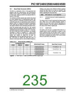
The Enhanced USART module supports the automatic
detection and calibration of baud rate. This feature is
active only in Asynchronous mode and while the WUE
bit is clear.
2: It is up to the user to determine that the
incoming character baud rate is within the
range of the selected BRG clock source.
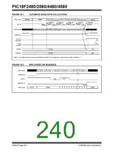
The automatic baud rate measurement sequence
(Figure 19-1) begins whenever a Start bit is received
and the ABDEN bit is set. The calculation is
self-averaging.
Some
combinations
of
oscillator
frequency and EUSART baud rates are
not possible due to bit error rates. Overall
system timing and communication baud
rates must be taken into consideration
when using the Auto-Baud Rate
Detection feature.
In the Auto-Baud Rate Detect (ABD) mode, the clock to
the BRG is reversed. Rather than the BRG clocking the
incoming RX signal, the RX signal is timing the BRG. In
ABD mode, the internal Baud Rate Generator is used
as a counter to time the bit period of the incoming serial
byte stream.
3: To maximize baud rate range, it is recom-
mended to set the BRG16 bit if the
auto-baud feature is used.
Once the ABDEN bit is set, the state machine will clear
the BRG and look for a Start bit. The Auto-Baud Rate
Detection must receive a byte with the value 55h
(ASCII “U”, which is also the LIN/J2602 bus Sync
character) in order to calculate the proper bit rate. The
measurement is taken over both a low and a high bit
time in order to minimize any effects caused by asym-
metry of the incoming signal. After a Start bit, the
SPBRG begins counting up, using the preselected
clock source on the first rising edge of RX. After eight
bits on the RX pin or the fifth rising edge, an accumu-
lated value totalling the proper BRG period is left in the
SPBRGH:SPBRG register pair. Once the 5th edge is
seen (this should correspond to the Stop bit), the
ABDEN bit is automatically cleared.
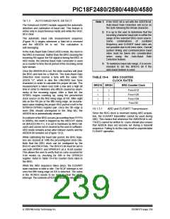
TABLE 19-4: BRG COUNTER
CLOCK RATES
BRG16 BRGH
BRG Counter Clock
0
0
0
1
FOSC/512
FOSC/128
1
1
0
1
FOSC/128
FOSC/32
19.1.3.1
ABD and EUSART Transmission
Since the BRG clock is reversed during ABD acquisi-
tion, the EUSART transmitter cannot be used during
ABD. This means that whenever the ABDEN bit is set,
TXREG cannot be written to. Users should also ensure
that ABDEN does not become set during a transmit
sequence. Failing to do this may result in unpredictable
EUSART operation.
If a rollover of the BRG occurs (an overflow from FFFFh
to 0000h), the event is trapped by the ABDOVF status
bit (BAUDCON<7>). It is set in hardware by BRG roll-
overs and can be set or cleared by the user in software.
ABD mode remains active after rollover events and the
ABDEN bit remains set (Figure 19-2).
While calibrating the baud rate period, the BRG regis-
ters are clocked at 1/8th the preconfigured clock rate.
Note that the BRG clock can be configured by the
BRG16 and BRGH bits. The BRG16 bit must be set to
use both SPBRG1 and SPBRGH1 as a 16-bit counter.
This allows the user to verify that no carry occurred for
8-bit modes by checking for 00h in the SPBRGH
register. Refer to Table 19-4 for counter clock rates to
the BRG.
While the ABD sequence takes place, the EUSART
state machine is held in Idle. The RCIF interrupt is set
once the fifth rising edge on RX is detected. The value
in the RCREG needs to be read to clear the RCIF
interrupt. ThecontentsofRCREG shouldbediscarded.
© 2009 Microchip Technology Inc.
DS39637D-page 239

 MICROCHIP [ MICROCHIP ]