PIC18CXX2
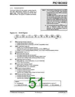
4.13.1 RCON REGISTER
Note 1: If the BOREN configuration bit is set, BOR
is ’1’ on Power-on Reset. If the BOREN
configuration bit is clear, BOR is unknown
on Power-on Reset.
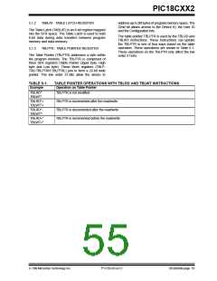
The Reset Control (RCON) register contains flag bits,
that allow differentiation between the sources of a
device reset. These flags include the TO, PD, POR,
BOR and RI bits. This register is readable and writable.
The BOR status bit is a "don't care" and is
not necessarily predictable if the brown-
out circuit is disabled (the BOREN config-
uration bit is clear). BOR must then be set
by the user and checked on subsequent
resets to see if it is clear, indicating a
brown-out has occurred.
2: It is recommended that the POR bit be set
after
a
Power-on Reset has been
detected, so that subsequent Power-on
Resets may be detected.
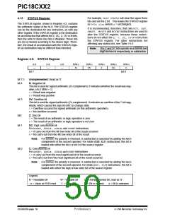
Register 4-3: RCON Register
R/W-0
IPEN
R/W-0
LWRT
U-0
R/W-1
R/W-1
R/W-1
R/W-0
R/W-0
—
RI
TO
PD
POR
BOR
bit 7
bit 0
bit 7
bit 6
IPEN: Interrupt Priority Enable bit
1= Enable priority levels on interrupts
0= Disable priority levels on interrupts (16CXXX compatibility mode)
LWRT: Long Write Enable bit
1= Enable TBLWTto internal program memory
Once this bit is set, it can only be cleared by a POR or MCLR reset.
0= Disable TBLWTto internal program memory; TBLWTonly to external program memory
bit 5
bit 4
Unimplemented: Read as ’0’
RI: Reset Instruction Flag bit
1= The Reset instruction was not executed
0= The Reset instruction was executed causing a device reset
(must be set in software after a Brown-out Reset occurs)
bit 3
bit 2
bit 1
TO: Watchdog Time-out Flag bit
1= After power-up, CLRWDTinstruction, or SLEEPinstruction
0= A WDT time-out occurred
PD: Power-down Detection Flag bit
1= After power-up or by the CLRWDTinstruction
0= By execution of the SLEEPinstruction
POR: Power-on Reset Status bit
1= A Power-on Reset has not occurred
0= A Power-on Reset occurred
(must be set in software after a Power-on Reset occurs)
bit 0
BOR: Brown-out Reset Status bit
1= A Brown-out Reset has not occurred
0= A Brown-out Reset occurred
(must be set in software after a Brown-out Reset occurs)
Legend:
R = Readable bit
W = Writable bit
U = Unimplemented bit, read as ‘0’
’0’ = Bit is cleared x = Bit is unknown
- n = Value at POR reset
’1’ = Bit is set
7/99 Microchip Technology Inc.
Preliminary
DS39026B-page 51

 MICROCHIP [ MICROCHIP ]