PIC18CXX2
For example, CLRF STATUSwill clear the upper-three
bits and set the Z bit. This leaves the STATUS register
as 000u u1uu(where u= unchanged).
4.13
STATUS Register
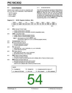
The STATUS register, shown in Register 4-2, contains
the arithmetic status of the ALU. The STATUS register
can be the destination for any instruction, as with any
other register. If the STATUS register is the destination
for an instruction that affects the Z, DC, C, OV or N bits,
then the write to these five bits is disabled. These bits
are set or cleared according to the device logic. There-
fore, the result of an instruction with the STATUS regis-
ter as destination may be different than intended.
It is recommended, therefore, that only BCF, BSF,
SWAPF, MOVFFand MOVWFinstructions are used to
alter the STATUS register, because these instruc-
tions do not affect the Z, C, DC, OVor Nbits from
the STATUS register. For other instructions not
affecting any status bits, see Table 19-2.
Note: The C and DC bits operate as a borrow and
digit borrow bit respectively, in subtraction.
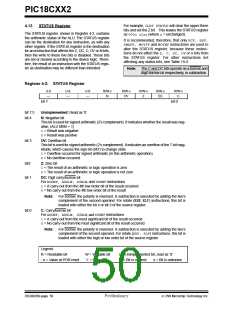
Register 4-2: STATUS Register
U-0
U-0
U-0
R/W-x
R/W-x
R/W-x
R/W-x
R/W-x
—
—
—
N
OV
Z
DC
C
bit 7
bit 0
bit 7:5
bit 4
Unimplemented: Read as ’0’
N: Negative bit
This bit is used for signed arithmatic (2’s complement). It indicates whether the result was neg-
ative, (ALU MSB = 1)
1= Result was negative
0= Result was positive
bit 3
OV: Overflow bit
This bit is used for signed arithmetic (2’s complement). It indicates an overflow of the 7-bit mag-
nitude, which causes the sign bit (bit7) to change state.
1= Overflow occurred for signed arithmatic (in this arithmetic operation)
0= No overflow occurred
bit2
Z: Zero bit
1= The result of an arithmetic or logic operation is zero
0= The result of an arithmetic or logic operation is not zero
bit 1
DC: Digit carry/borrow bit
For ADDWF, ADDLW, SUBLW, and SUBWFinstructions
1= A carry-out from the 4th low order bit of the result occurred
0= No carry-out from the 4th low order bit of the result
Note: For borrow, the polarity is reversed. A subtraction is executed by adding the two’s
complement of the second operand. For rotate (RRF, RLF) instructions, this bit is
loaded with either the bit 4 or bit 3 of the source register.
bit 0
C: Carry/borrow bit
For ADDWF, ADDLW, SUBLW, and SUBWFinstructions
1= A carry-out from the most significant bit of the result occurred
0= No carry-out from the most significant bit of the result occurred
Note: For borrow, the polarity is reversed. A subtraction is executed by adding the two’s
complement of the second operand. For rotate (RRF, RLF) instructions, this bit is
loaded with either the high or low order bit of the source register.
Legend:
R = Readable bit
W = Writable bit
’1’ = Bit is set
U = Unimplemented bit, read as ‘0’
’0’ = Bit is cleared x = Bit is unknown
- n = Value at POR reset
DS39026B-page 50
Preliminary
7/99 Microchip Technology Inc.

 MICROCHIP [ MICROCHIP ]