PIC18CXX2
14.3.3 MASTER MODE
14.3.4 I2C MASTER MODE SUPPORT
Master mode of operation is supported by interrupt
generation on the detection of the START and STOP
conditions. The STOP (P) and START (S) bits are
cleared from a reset or when the MSSP module is dis-
abled. Control of the I2C bus may be taken when the P
bit is set or the bus is idle with both the S and P bits
clear.
Master Mode is enabled by setting and clearing the
appropriate SSPM bits in SSPCON1 and by setting the
SSPEN bit. Once master mode is enabled, the user has
six options.
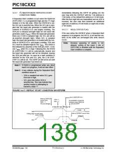
1. Assert a start condition on SDA and SCL.
2. Assert a Repeated Start condition on SDA and
SCL.
In master mode, the SCL and SDA lines are manipu-
lated by the MSSP hardware.
3. Write to the SSPBUF register initiating transmis-
sion of data/address.
The following events will cause SSP Interrupt Flag bit,
SSPIF, to be set (SSP Interrupt if enabled):
4. Generate a stop Condition on SDA and SCL.
5. Configure the I2C port to receive data.
• START condition
• STOP condition
6. Generate an acknowledge condition at the end
of a received byte of data.
• Data transfer byte transmitted/received
• Acknowledge Transmit
• Repeated Start
Note: The MSSP Module, when configured in I2C
Master Mode, does not allow queueing of
events. For instance, the user is not
allowed to initiate a start condition and
immediately write the SSPBUF register to
imitate transmission before the START
condition is complete. In this case, the
SSPBUF will not be written to and the
WCOL bit will be set, indicating that a write
to the SSPBUF did not occur.
2
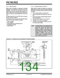
FIGURE 14-13: MSSP BLOCK DIAGRAM (I C MASTER MODE)
Internal
Data Bus
SSPM3:SSPM0
SSPADD<6:0>
Read
Write
SSPBUF
SSPSR
Baud
Rate
Generator
SDA
Shift
Clock
SDA in
MSb
LSb
Start bit, Stop bit,
Acknowledge
Generate
SCL
Start bit detect
Stop bit detect
Write collision detect
Clock Arbitration
State counter for
end of XMIT/RCV
SCL in
Bus Collision
Set/Reset, S, P, WCOL (SSPSTAT)
Set SSPIF, BCLIF
Reset ACKSTAT, PEN (SSPCON2)
DS39026B-page 134
Preliminary
7/99 Microchip Technology Inc.

 MICROCHIP [ MICROCHIP ]