PIC18F6525/6621/8525/8621
4.1.1
PIC18F6525/6621/8525/8621
PROGRAM MEMORY MODES
4.0
MEMORY ORGANIZATION
There are three memory blocks in PIC18F6525/6621/
8525/8621 devices. They are:
PIC18F8525/8621 devices differ significantly from their
PIC18 predecessors in their utilization of program
memory. In addition to available on-chip Flash program
memory, these controllers can also address up to
2 Mbytes of external program memory through the
external memory interface. There are four distinct
operating modes available to the controllers:
• Program Memory
• Data RAM
• Data EEPROM
Data and program memory use separate busses which
allow for concurrent access of these blocks. Additional
detailed information for Flash program memory and
data EEPROM is provided in Section 5.0 “Flash
Program Memory” and Section 7.0 “Data EEPROM
Memory”, respectively.
• Microprocessor (MP)
• Microprocessor with Boot Block (MPBB)
• Extended Microcontroller (EMC)
• Microcontroller (MC)
In addition to on-chip Flash, the PIC18F8525/8621
devices are also capable of accessing external
program memory through an external memory bus.
Depending on the selected operating mode (discussed
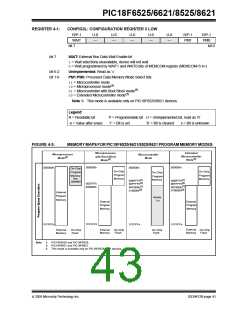
The Program Memory mode is determined by setting
the two Least Significant bits of the CONFIG3L
Configuration Byte register as shown in Register 4-1
(see Section 24.1 “Configuration Bits” for additional
details on the device configuration bits).
in
Section 4.1.1
“PIC18F6525/6621/8525/8621
Program Memory Modes”), the controllers may
access either internal or external program memory
exclusively, or both internal and external memory in
selected blocks. Additional information on the external
memory interface is provided in Section 6.0 “External
Memory Interface”.
The Program Memory modes operate as follows:
• The Microprocessor Mode permits access only
to external program memory; the contents of the
on-chip Flash memory are ignored. The 21-bit
program counter permits access to a 2-Mbyte
linear program memory space.
4.1
Program Memory Organization
• The Microprocessor with Boot Block Mode
accesses on-chip Flash memory from addresses
000000h to 0007FFh. Above this, external program
memory is accessed all the way up to the 2-Mbyte
limit. Program execution automatically switches
between the two memories as required.
A 21-bit program counter is capable of addressing the
2-Mbyte program memory space. Accessing a location
between the physically implemented memory and the
2-Mbyte address will cause a read of all ‘0’s (a NOP
instruction).
• The Microcontroller Mode accesses only
on-chip Flash memory. Attempts to read above the
physical limit of the on-chip Flash (BFFFh for the
PIC18FX525, FFFFh for the PIC18FX621) causes
a read of all ‘0’s (a NOPinstruction).
The PIC18F6525 and PIC18F8525 each have
48 Kbytes of on-chip Flash memory, while the
PIC18F6621 and PIC18F8621 have 64 Kbytes of Flash.
This means that PIC18FX525 devices can store inter-
nally up to 24,576 single-word instructions and
PIC18FX621 devices can store up to 32,768 single-word
instructions.
The Microcontroller mode is also the only operating
mode available to PIC18F6525/6621 devices.
• The Extended Microcontroller Mode allows
access to both internal and external program
memories as a single block. The device can
access its entire on-chip Flash memory; above
this, the device accesses external program
memory up to the 2-Mbyte program space limit.
As with Boot Block mode, execution automatically
switches between the two memories as required.
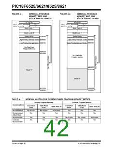
The Reset vector address is at 0000h and the interrupt
vector addresses are at 0008h and 0018h.
Figure 4-1 shows the program memory map for
PIC18FX525 devices, while Figure 4-2 shows the
program memory map for PIC18FX621 devices.
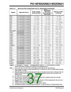
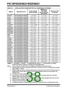
In all modes, the microcontroller has complete access
to data RAM and EEPROM.
Figure 4-3 compares the memory maps of the different
program memory modes. The differences between
on-chip and external memory access limitations are
more fully explained in Table 4-1.
2005 Microchip Technology Inc.
DS39612B-page 39

 MICROCHIP [ MICROCHIP ]