PIC18F6525/6621/8525/8621
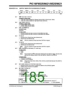
REGISTER 18-3: SSPSTAT: MSSP STATUS REGISTER (I2C MODE)
R/W-0
SMP
R/W-0
CKE
R-0
D/A
R-0
P
R-0
S
R-0
R-0
UA
R-0
BF
R/W
bit 7
bit 0
bit 7
SMP: Slew Rate Control bit
In Master or Slave mode:
1 = Slew rate control disabled for Standard Speed mode (100 kHz and 1 MHz)
0 = Slew rate control enabled for High Speed mode (400 kHz)
bit 6
bit 5
CKE: SMBus Select bit
In Master or Slave mode:
1= Enable SMBus specific inputs
0= Disable SMBus specific inputs
D/A: Data/Address bit
In Master mode:
Reserved
In Slave mode:
1= Indicates that the last byte received or transmitted was data
0= Indicates that the last byte received or transmitted was address
bit 4
bit 3
bit 2
P: Stop bit
1= Indicates that a Stop bit has been detected last
0= Stop bit was not detected last
Note:
This bit is cleared on Reset and when SSPEN is cleared.
S: Start bit
1= Indicates that a Start bit has been detected last
0= Start bit was not detected last
Note:
This bit is cleared on Reset and when SSPEN is cleared.
R/W: Read/Write bit Information (I2C mode only)
In Slave mode:
1= Read
0= Write
Note:
This bit holds the R/W bit information following the last address match. This bit is only
valid from the address match to the next Start bit, Stop bit or not ACK bit.
In Master mode:
1= Transmit is in progress
0= Transmit is not in progress
Note:
ORing this bit with SEN, RSEN, PEN, RCEN or ACKEN will indicate if the MSSP is
in Idle mode.
bit 1
bit 0
UA: Update Address bit (10-bit Slave mode only)
1= Indicates that the user needs to update the address in the SSPADD register
0= Address does not need to be updated
BF: Buffer Full Status bit
In Transmit mode:
1= SSPBUF is full
0= SSPBUF is empty
In Receive mode:
1= SSPBUF is full (does not include the ACK and Stop bits)
0= SSPBUF is empty (does not include the ACK and Stop bits)
Legend:
R = Readable bit
-n = Value at POR
W = Writable bit
‘1’ = Bit is set
U = Unimplemented bit, read as ‘0’
‘0’ = Bit is cleared x = Bit is unknown
2005 Microchip Technology Inc.
DS39612B-page 183

 MICROCHIP [ MICROCHIP ]